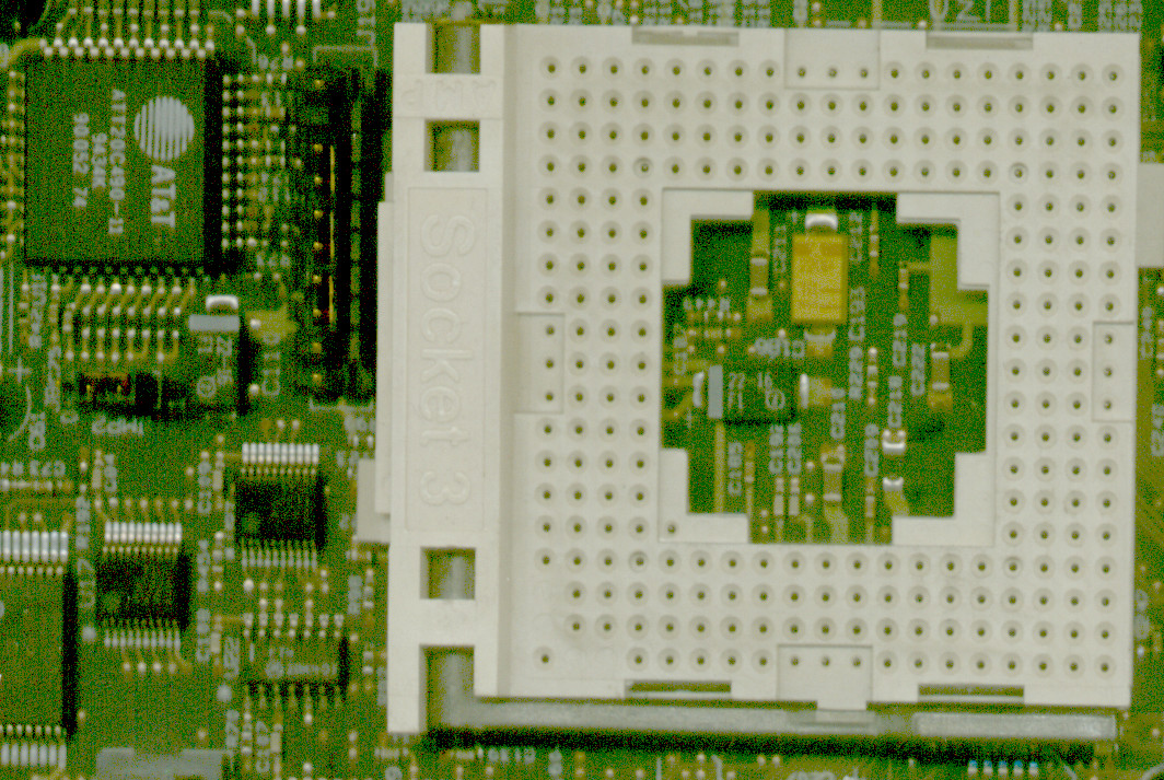
Except for the DX4, all supported CPUs need a standard 5V supply. For the DX4, Intel shrunk the whole chip and reduced the supply voltage to 3.3V . Such a technique is common to make chips faster, since the smaller structures have lower parasitic capacitances and shorter signal paths. Furthermore, the lower supply voltage reduces the chip's power consumption which otherwise would rise linearly with the clock frequency. Thankfully, the DX4 CPU's signal pins are 5V-tolerant, i.e. they can handle a 'high' signal level of 5 Volts without being damaged (something that is not self-evident for CMOS chips!). Therefore, getting a DX4 to run in a 5V system designed for older DX and DX2 CPUs simply involves putting a voltage regulator into the CPU's power supply. The Lacuna planar already has a socket for such a Voltage Regulator Module near the CPU socket; it is normally bridged with three jumpers to feed the 5V directly to the CPU. Below is a picture of this socket, located between the Video DAC and the CPU socket:
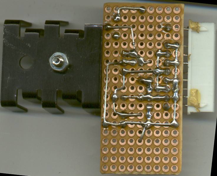
So if you upgrade a Lacuna to a DX4, just remove the jumpers, get the VRM module from IBM...ahem...which might be difficult or at least costly these days. I therefore built my own VRM, which is described below. It is not that difficult since there are voltage regulator chips available that only need a few external components, and building such a circuit on a prototype board is not that difficult when you're good at a soldering iron:
The 1085 belongs to the class of low-drop regulators, i.e. it still works reliably with voltage differences of less than a Volt between the input and output. Traditional regulators like the 78xx series or the LM317 adjustable regulator need a minimum voltage drop of 2 Volts between input and output, something we do not have in our situation (5V - 3.3V = 1.7V !). The other alternative of getting 12V from a drive power connector would give us enough voltage drop for a standard regulator, but result in a very hot circuit: suppose the CPU draws about 2 Amps, then the regulator will dissipate (12V - 3.3V) * 2A = 17 Watts, about three times as much as the CPU itself consumes!!! With 5V as input voltage, we get (5V - 3.3V) * 2A = 3.4 Watts, something easily handled with a small heatsink screwed onto the regulator.

As I said the circuitry is rather simple; most of the components are to protect the regulator. Worth describing are the resistors and the pot: the LT1085 has an internal voltage reference of about 1.5V, and the regulating circuitry tries to keep this constant voltage between terminals 1 and 2. Given that the current flowing into terminal 1 is negligible, the voltage drop over all three resistors (which is the output voltage) is proportional to the relation of the 120 Ohms resistor to the sum of all resistors. With 120 Ohms ~ 1.5V, 3.3V ~ 264 Ohms, which means that the 'lower half' of the resistor chain has to be trimmed to 144 Ohms. Since all resistors and the LT1085's voltage reference have tolerances, the combination of a pot and a fixed resistor allows a variation between ~2.5V and ~5V, enough to trim out all tolerances. Of course, the top limit of 5V cannot be reached because of the minimum voltage drop over the LT1085.
All other components are protective devices: The generous caps keep the LT1085 from oscillating and improve the output voltage's stability: As every voltage regulator, the LT1085 contains a back-coupled error amplifier that may swing if it isn't dampened sufficiently. The 1N4001 diode protects against the situation when the input voltage drops below the output voltage; this may happen when you turn the machine off and the 5V supply drops faster than the 3.3V output voltage. In such a situation, the diode allows the 3.3V capacitor(s) to discharge into the 5V supply, limiting the LT1085 backward bias to about 0.7V .
I therefore cut off the wires, and directly soldered small pieces of stiff wire to the plug's connectors. I then bended the wires by 90 degrees and soldered them into the prototype board. This way, the whole module is held upright by the wires and is nicely placed in the power supply's airflow. Below is a picture of my module:

When etching your own PCB, do not forget to make the traces to terminals 3 and 2 wide enough (> 1mm). As a rule of thumb, a trace of 1mm width can carry up to 1..1.5 Amps.
This picture shows the VRM module installed in a Model 76i:

Adjusting the output voltage is both possible with an external power supply and in the machine. If you want to adjust the module after putting it into the machine, remove the CPU from the socket before turning on again. Adjust the output voltage to 3.3...3.45V, the exact value is dependent on the version and revision of your DX4 CPU. To measure the output voltage, use a digital voltmeter since this is more precise than with an analog one. The output voltage can conveniently be measured at the LT1085's heat sink. Once this is done, you may verify the the 3.3V really arrive at the 486 CPU socket (you will need a 486 pinout for this, which should be available from Intel).
After verifying everything twice, turn the machine off, insert the CPU and verify the correct orientation. There are 4 possible ones, but only one of them works and doesn't potentially fry the planar!
Turn the machine on again. The Big Blue IBM screen should come up instantly. If not, turn off immediately! If everything went correct, the machine might report an equipment change error and send you into the configuration. Don't use automatic configuration, select 'Set Configuration/Change Configuration' to get into manual configuration. The planar's configuration should now show the DX4 CPU. Save the new configuration with F10 and leave the configuration. Congratulations, you are done!
Judging from these results, I doubt that AMD's DX4-100 will work; its power management differs from the Intel chip even more than the Am5x86's one, and the performance win compared to the Intel DX4 is substantially lower: AMD didn't include the larger 16K internal cache and the better integer processing unit, they just increased the clock speed. Mysteriously, others have reported that an AMD DX4 works for them - maybe I have to fiddle a bit with interposers...comments wanted!
Regarding the Cyrix 'Super-486' chips: I have a report by Guenter Harp that a Cyrix 5x86 works nicely in his 9577.