Click here or click onto the photo for a full size version of this picture.
| Pin | Industry Standard | IBM |
|---|---|---|
| 2 | Data CAS | Data&Parity CAS |
| 24 | Not Connected | Presence Detect |
| 26 | Parity Data Out | Presence Detect |
| 28 | Parity CAS | Not Connected |
| 29 | Parity Data In | Parity Data In/Out |
The two presence detect pins allow the following combinations:
| Pin 24 | Pin 26 | Capacity |
|---|---|---|
| open | open | no module inserted |
| open | grounded | 512Kx9 |
| grounded | open | 256Kx9 |
| grounded | grounded | 1Mx9 |
These modules have not only been used for the cached SCSI controller, but also in some early PS/2 machines for main memory, namely in the ISA-based Model 30-286, and the MCA-based 50/60 (not the newer 50Z which already uses 72-pin modules). Watch out however to use the correct type of modules for this purpose, see below!
In my experience, these modifications are simpler if you use 1M SIMMs built with 3 chips instead of 9; the three chips occupy less space on the module's PCB, and it is easier to get access to the connections. However, if you are going to modify modules to extend a Model 30 or 50, you will have to use 9-chip modules; The memory controllers of these old systems do not provide enough refresh address lines for the higher-capacity 1Mx4 chips on a 3-chip module, and you will experience strange memory errors with them. Not all 9-chip modules can be modified; the high chip density leads to a complex layout, and some of the traces that have to be cut might be located in inner layers...
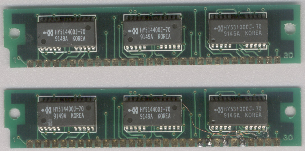
Shown below are two SIMMs; one unmodified and a SIMM that has been modified according to the instructions above.
Click here or click onto the photo for
a full size version of this picture.
These modules are typical for 3-chip industry-standard SIMMs. They consist of two 1Mx4 chips for the data (the 514400 chips) and an extra 1Mx1 chip (the 531000 in this case) for the extra parity bit. This in sum makes the usual 1Mx9 people are talking about...the names of the individual chips may vary wildly from module to module since the DRAM manufacturers are quite creative at this :-)
Luckily, there are ANSI standards for RAM chip pinouts, so I can give you a schematic rewiring plan here, both for 3-chip and 9-chip modules. The red lines show connections to be added, while the fat double red lines symbolize connections to be cut. Of course, there are more traces on a SIMM than the ones shown, but I left the ones out that need not be modified to make things a bit simpler.
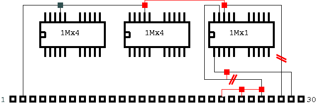
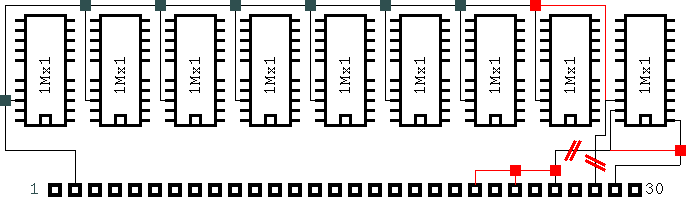
CAUTION!!! The pinouts of the individual chips apply only to your SIMMs if the chips are housed in the same case type (called 'SOJ') as for my modules!!!
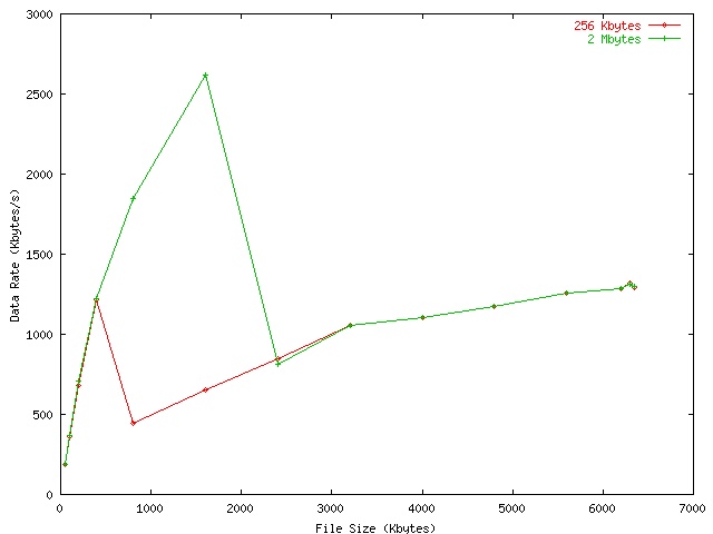
For file sizes smaller than 256 Kbytes or larger than 2 MBytes, the results do not differ: Either the working set fits into both sizes, or it is to large for both. The differences in the area between these margins is however remarkable: They result both from the higher RAM-to-RAM than Disk-to-RAM data rate and from the lower access time (the half rotation needed in average before the first data sector comes by is eliminated plus the SCSI protocol overhead). One can extrapolate that for a larger cache, the curve could well extend into the range of 5 to 10 Mbytes per second. However, Spock has no provisions to use 4 Mbyte modules; honestly said, I was already surprised that 2 MByte cache work. The 80188 processor only has a 1 MByte address space so there must be some sort of bank switching mechanism on the controller's memory interface; this wouldn't have been necessary for a 512K-only design.
Looking at linear accesses, the differences are not as impressive, but still visible:
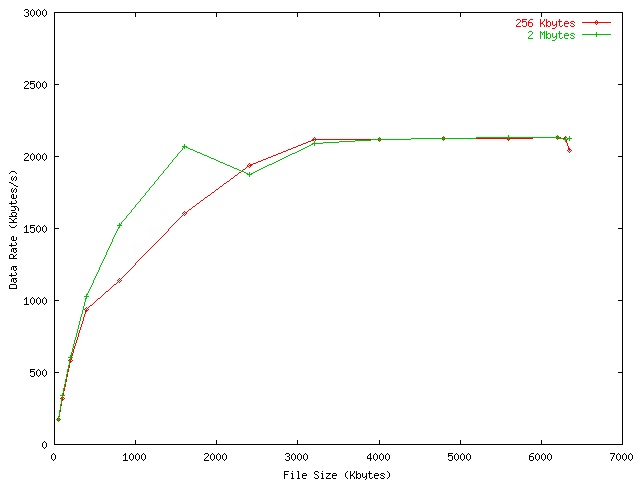
Though the cache cannot avoid repeated disk accesses to the same disk sectors, there is still a gain from the cache due to its read ahead capability: the controller reads data in larger chunks than the main CPU really requests them, and when the next chunk is requested, the controller can already deliver its beginning without overhead. Operation with no or too few cache is not as bad as in the random case as the drive's head only have to move by one cylinder.