
The most obvious thing - of course - is the relatively low output power of 'only' 2x50 watts RMS. Though this might seem sufficient for most home uses, it may become a problem when using more 'advanced' speakers, which usually have a lower efficiency and need a large amp. For example, the RA 200 of the lower-class T 200 system delivers 2x70 watts, and its immediate precedecessor, the STM 1/CM 20, even 2x85 watts.
Other things are maybe less obvious, but still annoying. For example, the RM 300 has connectors/clamps for two pairs of speakers, but they cannot be operated simultaeously. All other Telefunken amps with two speakers connectors had this option, so why not the RM 300? It can't be a question of overloading the amp, since in an 'A+B' setup, the speakers are connected in series, so the amp's load is even lower than with a single speaker pair.
Furthermore, the RM 300 lacks the LED VU meters known from all 'better' Telefunken amps. Though some people regard them as superfluous gimmicks, they are usually a good selling argument and it is difficult to understand why they were left out.
A closer investigation of its innards reveals that the RM 300 is a derivative of the CA 10, a smaller integrated amplifier of the 1980 series of Hifi systems. Is it possible that some options on the PCBs were simply left unpopulated for the RM 300 and wait for being discovered? Let's see...
A closer investigation of the RM300's schematics reveals that this relay gets engaged when both switches are on. The CA 10 even has this third relay! Below is a simplified schematic about how the this relay operates in conjunction with the other two:
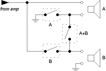 As one can see, speaker pair B's relay intercepts the speaker's 'hot'
wire, while speaker pair A's relay intercepts the speaker's
ground wire. If both switches are pressed, the 'A' and 'B' relays
are both off, and the 'A+B' relay connects both speakers in series. The
huge advantage of this approach is that it requires only one relay contact
per channel, so the whole circuitry gets along with three relays that have
simple '2xON' contacts. On the minus side, it is crucial that not all
three relays get operated at the same time; while operating any two relays
at the same time is uncritical (and very well possible as a transitional
state), turning all three relays on will short the amplifier's output!
As one can see, speaker pair B's relay intercepts the speaker's 'hot'
wire, while speaker pair A's relay intercepts the speaker's
ground wire. If both switches are pressed, the 'A' and 'B' relays
are both off, and the 'A+B' relay connects both speakers in series. The
huge advantage of this approach is that it requires only one relay contact
per channel, so the whole circuitry gets along with three relays that have
simple '2xON' contacts. On the minus side, it is crucial that not all
three relays get operated at the same time; while operating any two relays
at the same time is uncritical (and very well possible as a transitional
state), turning all three relays on will short the amplifier's output!
The switch logic theoretically prohibits such a situation, but I was not
entirely sure about this and inserted additional 1 Ohm / 5 W resistors
in series with the 'A+B' relay. Everyone has to decide for himself whether
these resistors are necessary; the CA 10 does not have such resistors.
For one channel, inserting the resistor was quite simple because it just meant soldering in the resistor in place of a wire bridge; for the other channel, I had to cut a trace on the PCB and drill an additional hole. Below is a photo how the 'enhanced' speaker PCB:

It is not necessary to find the exact same Rapa or Siemens relays that Telefunken used; this type of relay size and pinout seems to be a standard type that is manufactured by a couple of companies; I bought relays made by Schrack in an electronics store that had '2xUM' contacts, but it was simply a matter of clipping off the unneeded pins. Just be sure that you get relais wit 24V-coils!
| Pin Number | Signal |
|---|---|
| 1406 | right channel via R 430 |
| 406 | left channel via R 1430 |
| 508 | positive supply (+33V) via DB 430 |
| 507 | ground |
| 509 | negative supply (-33V) via DB 428 |
The positive regulator transistor also supplies the LED driver chips, so it need a small heatsink, while the negative supply only has to deliver a few milliamps to the OpAmp. There is plenty of space in the RM 300, so the board has a generous size:

About the choice of the LED drivers: Telefunken originally used its own U 237 / U 247 combo in the STM 1, which is however not available these days any more. The 'good old' UAA 180 however can still be had, and it can drive up to 12 LEDs.
The question still remains why Telefunken included provisions for a feature and never used it. In case of the CA 10, the answer might be simple: the front is full, it would have been difficult to fit in the LED VU meters somewhere. That is not true for the RM 300, it has plenty of space. So the only idea I have is that either the designers had to hit a certain price tag, and the VU meters just like the relay simply didn't fit any more on the bill.
Of course, the reason might simply be an aesthetic one: The whole T 300 system is marked by its timeless and elegant design. A flickering LED display without a necessary function simply disturbs this approach. I probably wouldn't have done this either, hadn't the previous owner already made the necessary cutouts in the front...
