
Modern integration has allowed to realize much higher powers with monolithic circuits, so hybrid circuits have become much rarer in cheap Hi-Fi equipment - and they never were used in better equipment, partly because of the bad reputation these hybrid modules had and have in Hi-Fi enthusiasts' circles.
For example, there was a series of hybrid circuits in Technics amplifiers that had the habit of blowing one of the internal final transistors after a few years. Since the DC protection was integrated into the hybrid and based on turning off the final transistors electronically, a defect in this hybrid typically also killed the speaker :-(
Telefunken has used the two strongest devices with symmetric supply: The 2x40W STK465 in the RA100, and the 2x30W STK463 in the RR100. However, due to the pin-compatibility, you may also find an STK465 in an RR100, which is of course still running with the lower supply voltage and will also deliver only 2x30W.
Both devices show similar typical failures: one of the internal final transistors breaks, which means that one of the outputs will now lead +30 or -30 volts DC. Thankfully, the DC protection circuit is external and turns off the output via a relay. Of course this relay is common for both channels, so the amp will be entirely silent...
At least for the RA100, you have no other chance than replacing the complete hybrid, since this device is extremely space-constrained. The RR100 however has a heatsink that offers a lot of space, which opens another option if you have more than one broken hybrid available: take two hybrids, and use the working halves to get a working stereo receiver again! Especially these days, replacement parts are more and more difficult to obtain, and what do you have to loose?
While this is basically not difficult, it requires a bit of mechanical rework in detail. Let's cover this first, but the usual disclaimer has to lead:
If you are intending to do what I describe here, you are entirely doing it at your own risk! It works for me, but keep im mind that you are working with components that are halfway broken, so there is no guarantee that this is a durable repair!
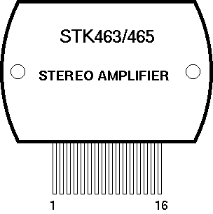
| Pin # | Function |
|---|---|
| 1 | Positive Input A |
| 2 | Negative Input A |
| 3 | Preamp Ground A |
| 4 | Feedback A |
| 5 | Negative Supply (Final Stage A) |
| 6 | Negative Output A |
| 7 | Positive Output A |
| 8 | Positive Supply (Preamp Stages) |
| 9 | Positive Supply (Final Stages) |
| 10 | Positive Output B |
| 11 | Negative Output B |
| 12 | Negative Supply (Final Stage B) |
| 13 | Feedback B |
| 14 | Preamp Ground B |
| 15 | Negative Input A |
| 16 | Positive Input B |