 |
 |
A few years ago Vintage Micros sold non-working Lisa keyboards for $19,99 each. A good price, so I ordered a few. They arrived, and as John promised, none of them worked! So I had to start a repair session. Though the repair procedure is not difficult, it usually takes a few attempts to find the correct foam and disk materials, correct size, glue etc. This means modify the keyboard, go to the Lisa, connect it, power up, try it, power down, disconnect, go to the desk, and so on. Therefore, after a very short time, I wanted a tool to test the keyboard on the bench, without having to use the precious computer.
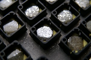
Most Apple II and Macintosh keyboards use single ALPS switches soldered to a PCB. The Lisa keyboard does not. It was build by KeyTronic and uses their unique capacitive sensing technology. Every key consists of three parts: two copper areas on the PCB surrounded by a guard track, and a metallized mylar disk mounted to the key plunger. Scan pulses are sent by an Exar XR 22-950-3B scan driver to one of the copper areas, the other one is connected to an Exar XR 22-908-03 sense amplifier. When a key is pressed, the mylar disk comes close to the copper areas and charge from the scan pulse is transferred into the sense amp. This procedure is controlled by an i8049 microcontroller that collects the data and sends it down to the Lisa.
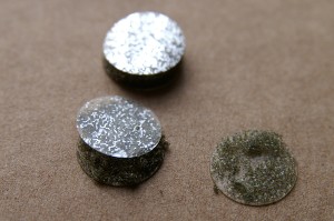
After some twenty years of service, these keyboards usually fail. The elastic foam that connects the mylar disk to the key plunger converts into something slimy and the disk either falls off or just does not reach the copper areas anymore. Sometimes the metallization of the disks fades, too. Both foam and disk can be replaced, the procedure is described in Ray's Lisa FAQ. Note that the size of the disk (7/16" resp. 11 mm) is critical, and also not all materials work equally well. Aluminium foil covered with Scotch or Tesa tape did not work as good as the silver plastic foil from a crisps bag. The outside of the foil has to be insulated, it is just for charge transfer, not for an galvanic connection!
|
|
I started with simple polyurethane cushion foam, the stuff that is used as packing material. The results were not satisfying. Cellular rubber ("Zellkautschuk") is an excellent material, but rather expensive. A good alternative is polyethylene (PE) foam. I bought mine at Gerkaplast.
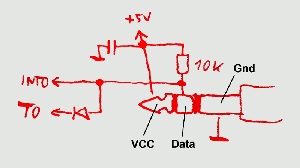
The keyboard connects to the Lisa through a 1/4" audio jack. Tip is +5 Volts, right channel ring is Data, and Ground ring is Ground. Data is transferred as open-collector TTL, i.e the unused channel is pulled up to 5 Volt through a resistor, and anyone who wants to send data pulls the line down below 1 Volt.
Every millisecond, Lisa generates a 20 µs SYNC pulse on the data line. Whenever the keyboard has detected a keypress, it responds with a data telegram. Approximately 40 µs after the beginning of the SYNC pulse a start bit is transmitted, then eight data bits follow. The data bits are inverted and their order is somewhat unusual: /D4, /D5, /D6, /D7, /D0, /D1, /D2, /D3. Each bit has a duration of 16 µs, except for bit 7 (the fourth one transmitted), which is 30 µs long. So the whole transmission takes 158 µs.
Every keypress generates two data telegrams: one when the key is pressed (make code), and one when the key is released (release code). This is an easy way to allow any multiple keypresses at the same time, like <shift><apple><s>. A make code always has bit 7 set, a release code has bit 7 cleared. The scancode table for an US keyboard looks like this:
; *******************************************************************
;  Scan Code Table
; *******************************************************************

0300	79 7E 70 7D 74 68 78 75		; Z     Shft  A     ALck  1!    `~    Tab  Q
	7E 00 00 48 45 41 57 42 	; Shft              Retn  Bksp  =+    ]}   \|
	00 4C 5B 5A 40 51 44 56		;       /?    '"    ;:    -_    0)    P    [{
	00 00 00 00 00 00 00 00
	00 00 00 00 00 00 00 00
	6E 6C 6A 69 64 73 65 66 	; B     V     G     F     5%    4$    R     T
	58 6F 54 6B 62 61 67 52		; M     N     J     H     7&    6^    Y     U
	5E 5D 59 55 50 63 53 5F 	; .>    ,<    L     K     9(    8*    I     O
	43 2C 49 4E 7F 7C 5C 46		; <>    .     0     ROptn Apple LOptn Spc   Enter
	6D 7A 7B 76 72 71 77 60 	; C     X     D     S     3#    2@    W     E
	2F 2E 2B 2A 23 22 26 27		; NRtn  3     +     6     =     *     9     /
	2D 4D 29 28 21 20 24 25		; 2     1     5     4     -     Clr   7     8
Immediately after Reset or power-up, an ID code is transmitted to the Lisa. Based on this code, the language of the power-on self test is selected. The Layout ID can be set by a jumper and a DIP switch on the keyboard PCB. The jumper defines whether an US or international keyswitch assemby is fitted (the US has a rectangular, the international a L-shaped Return key). With the DIP switch, one of sixteen international layouts can be selected. The following combinations were supported by Apple:
; After Reset, the keyboard sends an ID byte, 080h followed by the
; Layout ID. 0FFh is sent as ID when the internal selftest failed.
;
; Layout ID codes:  10zyxxxxb
;   0BFh = US         ||  |
;   0AFh = UK         ||  +--- P2.3-0: DIP SW
;   0AEh = German     |+------ P2.4: 1= US, 0= Intl.
;   0ADh = French     +------- P2.5: unused, =1
;
; KData input is -INT, KData output is P2.7
; scan driver XR 22-950-3B is connected to P1.0-3 & PROG
; sense amplifier XR 22-908-03 is connected to P1.0-7 & PROG
; ===================================================================
; Jumpers:
;   E1-E2:	EA (closed)
;   E3-E4:	P2.5 (open)
;   E5-E6:	P2.4 (open US, closed Intl.)
; ===================================================================
To force a keyboard reset, pull down the Data line for 5 ms.
I did not find any detailed (and correct) documentation on the keyboard circuit and firmware, so I had to perform my own research on a Keytronic A65-02592-055, firmware v5.12. There may be some errors in my tables shown above. Nevertheless, the information given in the Lisa Hardware Manual is a good deal worse.
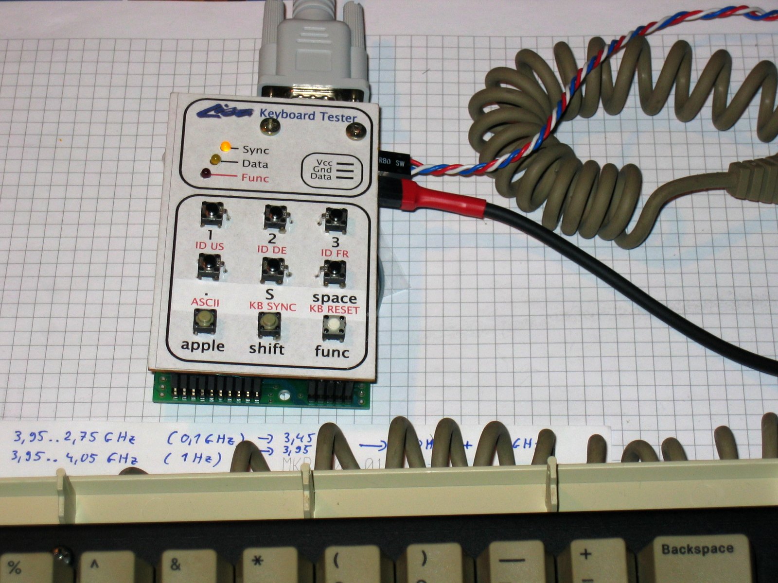
My Keyboard Tester can be used in two ways:
as a keyboard monitor that dumps anything that comes from the keyboard to a RS-232 port. Data can be displayed as scancodes or ASCII.
as a keyboard simulator that sends data from RS-232 to the Lisa. Besides that, the unit has eight local keys: <1>, <2>, <3>, <.>, <S>, <space>, <apple>, and <shift>. Eight keys are not a full keyboard, but sufficient for the power-on self test and the boot menu.
It would not be difficult to replace the RS-232 with a PS/2 port and build a PS/2-to-Lisa keyboard converter, but who needs that? I don't want to see any PC stuff in my Apple collection (though I use it sometimes internally, see IDEfile).
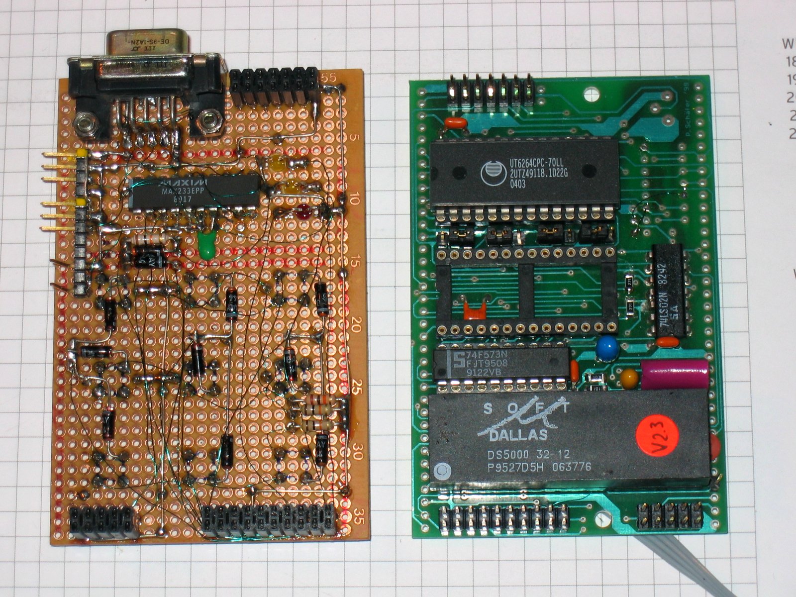
The heart of the Keyboard tester is an i8031 microcontroller, running 900 lines of assembler code. It scans a 3x3 keypad, three status LEDs and of course the keyboard interface and the RS-232C port. Shown below is a schematic diagram of the unit, click on the image for a full-size pdf.

I built this using parts I had on stock. This is also the reason why there is no PCB artwork - I took an old 8031 prototyping board and sandwiched a Vero breadboard onto it which holds the LEDs and keys. In case you want to build your own and you have to buy the parts, I stronly recommend using a controller with internal flash memory (like Atmel's AT89C51-24PI). This allows you to skip the parts located right of the controller. Crystal frequency is 11.0592 MHz and the controller has to be one of the regular divide-by-12 type, otherwise the timing would not be correct.
Note that there is a static RAM in the schematic and on the board. However, it is not used by the software. If one is fitted, the RAM test will display its size and that's all.
J1 is the RS-232C port. Pinning allows a direct connection to a crimped Sub-D9 female, which connects by a 1:1 extension cable to the host. The tester communicates at 19200 baud, 8 bit, no parity.
J2 and J3 are identical three-pin headers which connect either to a cable with a 6.3 mm stereo phono plug (to connect the tester to a Lisa) or to a cable with a 6.3 mm stereo phono socket (to connect a keyboard) and to a second cable which provides +5 V and Gnd. You have to apply this voltage in stand-alone mode, when testing keyboards, but you must not apply it when the tester is connected to a computer!
 |
 |
If you want to copy my assembly style, print FrontOverlay.pdf on a piece of paper and glue it onto the Vero board. Then pierce the pushbuttons and LEDs through the paper and solder them to the board. Mount the rest of the components on the back, and use a second board as the bottom.
KBTST101.OBJ is the binary file with the firmware for the controller. This is no open source code, but may be used free of charge for personal and educational purposes.
As mentioned before, the Keyboard Tester may be used in two ways: to test a Lisa keyboard with your PC, or to emulate a Lisa keyboard with your Lisa.
Connect J1 to your computer's serial port. Start your favourite terminal program and set communication parameters to 19200 baud, 8 bit, no parity. Apply power to the tester, and you should see something like
Lisa Keyboard Tester V1.01
 (c) Dr. P. Schaefer, 2008

1FFFh bytes RAM found.
RAM ok.

ready.
Press the tester's <func> key. The Func LED should turn on. Press it again, the LED should turn off. Press <func>, then <S>. The Sync LED should turn on. Repeat this to switch it off. Now connect your keyboard.
Press <func>, then <S> to turn on the SYNC pulse. The keyboard will send its Layout ID code:
US Keyboard connected.
Now press any (working ;-) key on the keyboard. The Data LED should flash briefly whenever a key is pressed or released, and the ASCII value of the key should be printed on the terminal screen. Control keys are represented by lowercase letters.
Press <func>, then <.> to switch into scancode mode. The data sent by the keyboard will now be printed as hex values, one when a key is pressed, and a second when the key is released. Pressing <func>, then <.> again switches back to ASCII mode.
Connect the tester to the Lisa's keyboard jack. Turn on the Lisa. Don't apply any power to the tester, it is supplied by the computer. Now use the eight keys <1>, <2>, <3>, <.>, <S>, <space>, <apple>, and <shift> exactly as you would do on your regular keyboard.
Pressing <func> then <1>, <2> or <3> sends an US, German or French ID code.
If this is not enough, run a serial line to your computer and start your terminal program. Enter <t> to switch on the RS232 Keyboard mode. Now everything you type on the serial line is converted into scancodes and sent to the Lisa. As you should know, a Lisa keyboard generates two scancodes for each keypress. A make code when the key goes down, and a release code when it is released. On the RS-232 line we have only one character per keypress. This does not allow you to enter multiple-key commands like <apple><.>. To overcome this limitation, some terminal characters have different functions:
| shift-Q: | press <shift> key (send make code) |
| shift-A: | release <shift> key (send release code) |
| shift-W: | press <apple> key (send make code) |
| shift-S: | release <apple> key (send release code) |
| shift-E: | press <option> key (send make code) |
| shift-D: | release <option> key (send release code) |
| ctrl-A: | send 0x55 |
| ctrl-B: | send 0xAA |
With this trick, these keys can be "pressed" before and "released" after any other. To enter <apple><.> you have to type shift-W, then the dot, and then shift-S. This actually sends the codes for <apple> down, <.> down, <.> up, <apple> up.
To leave the RS-232 keyboard mode, press the <space> key on the tester.
Note that SYNC has to be off because it is generated by the Lisa.
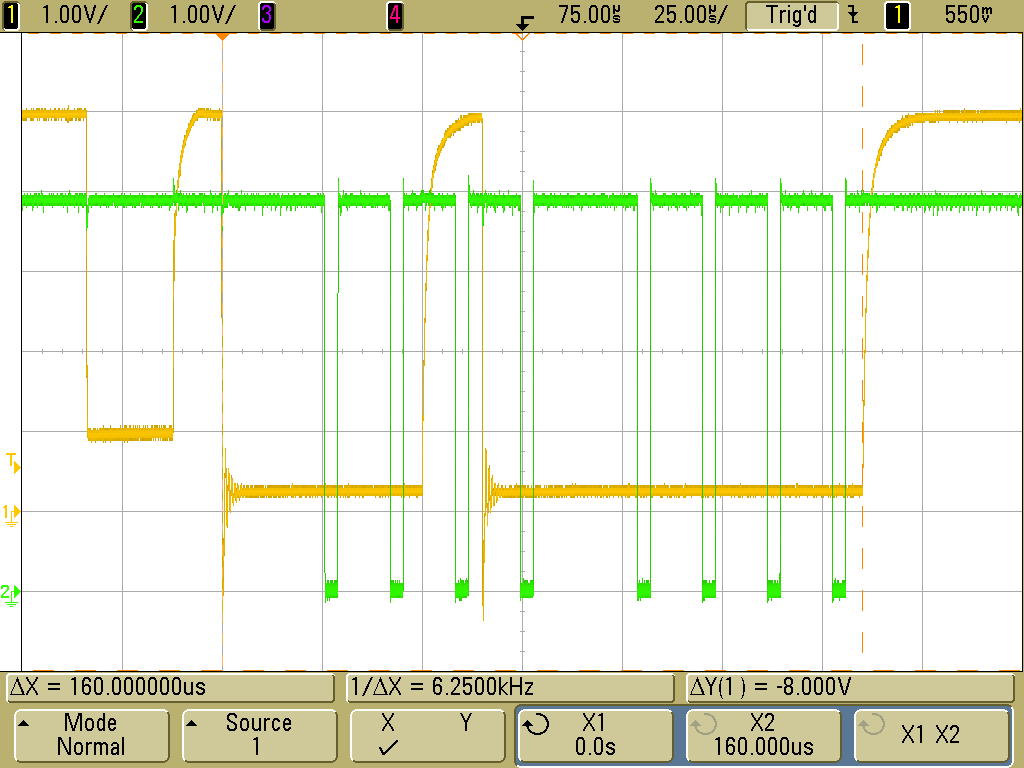
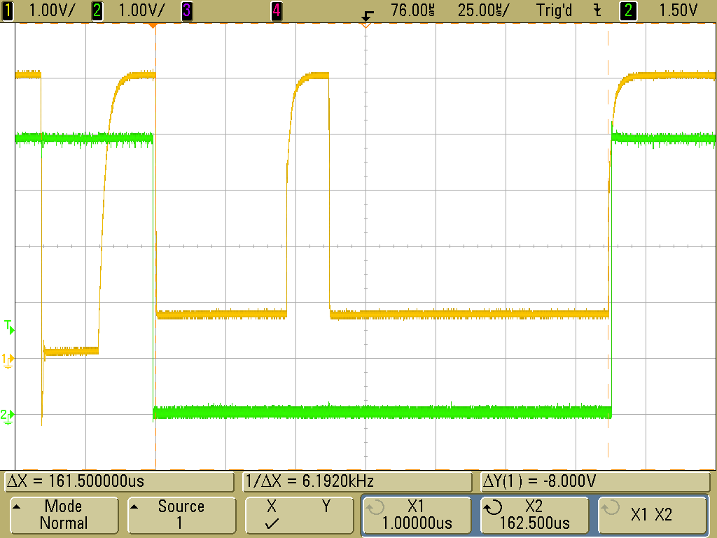
For the advanced user, three testpoints are provided. TP3 is ground, TP2 allows you to connect your oscilloscope to the Keyboard Data line. TP1 was used as a debug pin during software development and provides now some status information. Here is what you can see there (click on the images for original size):
 |
 |
Unlikely. This was a quick & dirty design that allows me testing keyboards on the bench. It works for me as it is now, so I won't spend any more time on it. Schematic and binary file are given here to allow you to build your own unit, but as usual, you do this on your own risk.
The program and circuitry given here are free for personal use, but are not in the public domain. Freeware in contrast to public domain means that while the author makes the product available for free, the copyright is still hold by the author. This does mean that you can build the circuit and use the software without paying any fees, but you may not sell or redistribute the software or the circuit design, neither unmodified nor versions derived from it, without prior written permission from the author.
I will give absolutely no guarantee that the software or circuit will work as described, that it will not destroy your computer, the circuit itself, or any peripherials connected to it. I also refuse any responsibilty for data losses resulting from the use of this software and circuit design. It's freeware. If you want some guarantee, buy a commerial product. It is explicitly prohibited to use the software and circuit described here in places where failure or malfunction may be dangerous to the health or result in monetary losses.
Lisa Keyboard Tester is copyright (c) by Dr. Patrick Schäfer, 2008
Apple, Lisa and the keyboard communications protocol are (c) by Apple Computer Inc.
----> Back to my home page