 |
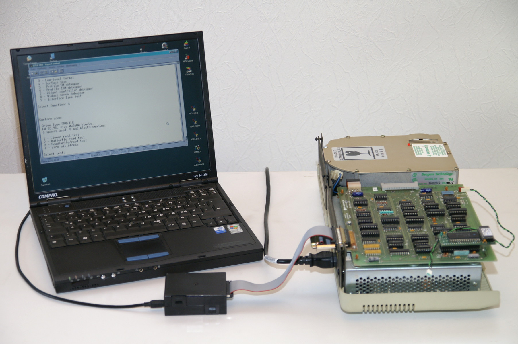 |
WidEx was the name of a tool Apple's Disk group used to format, debug and troubleshoot their Widget hard drives. It was written in Apple /// Pascal, somewhere in 1984. UsbWidEx is a modern representation of this tool. It is a stand-alone system based on a Renesas R8C/34 16 bit microcontroller, which connects to a PC or Mac via USB. A virtual COM port is emulated, so that any terminal program can be used to control it. UsbWidEx can be used to read or write single data blocks, to create backup images of a whole disk and write them back, and to send diagnostic messages to the drive controller and retrieve status information. If your drive tells you that it does't work anymore (by keeping its Ready light off), this tool is what you need to see what's going on. And on the lowest level, you can talk directly to the servo board and move the heads around the disk.
Some examples how this looks like can be found here.
|
|
ProFile and Widget drives are connected to their host by way of a parallel interface. A more detailed description of this interface is given in my IDEfile article. While IDEfile simulates the device side, UsbWidEx recreates the host interface, i.e. emulates a Lisa or an Apple /// with parallel interface card running special test software.
Any hard drive system consists of two parts: a controller board and the drive itself. The controller board acts as a link between the host and the drive. It gets commands like "give me block number 0x002F" from the host and translates them into the signals necessary to move the heads over the desired track, pick up the data stream, extract the requested data bytes, and pass them over to the host. The controller board may be physically integrated into the drive, or it may be a separate module. It must not be confused with the host interface inside the computer. MFM, RLL and ESDI drives have separate controller boards, IDE, SATA and SCSI have them embedded into the drive's PCB.
Both ProFile and Widget have separate controller boards. The ProFile controller is sitting on the power supply cage, next to the Seagate ST-506/9 HDA. This drive unit is rather dumb, it just contains the amplifier circuits required to read or write data and a stepper motor to move the heads. Though it bears the name "ST-506", its mechanism is not identical to a generic ST-506 MFM drive. For some reason nobody knows Apple requested a special stepper motor with double resolution. With a standard drive mechanism, ProFile would use only every 2nd track and the heads would bang into their endstop after 77 cylinders. Fortunately the much more common ST-412 is a fine replacement -- it has 306 cylinders. Skipping every second one leaves us the 153 we need.
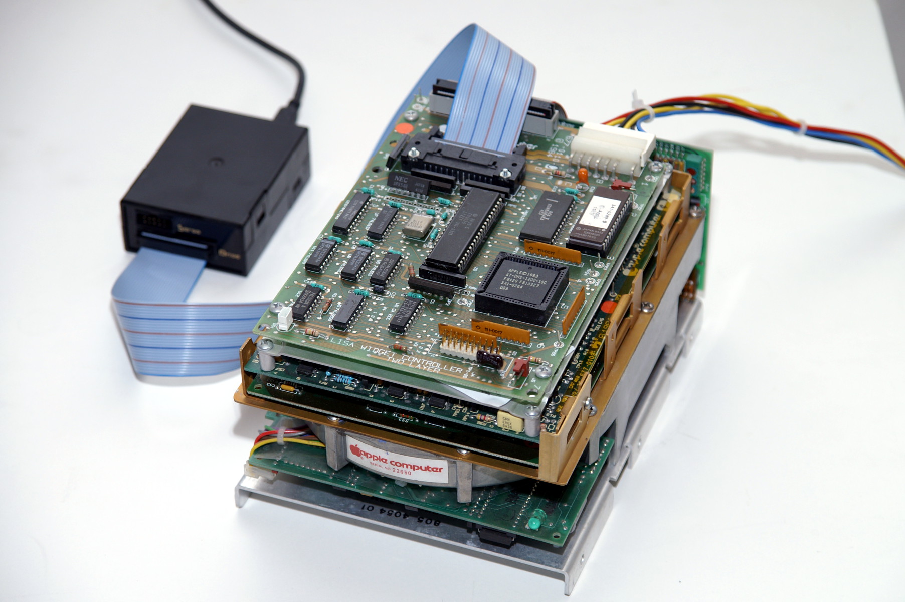
Looking at a Widget drive, you see five PCBs surrounding the HDA. Four of them belong to the drive itself, the fifth located on the top is the controller board. It is connected to the drive with a 40 pin flat cable. Widget's head positioning system is much more sophisticated -- it is a closed-loop servo with optical coarse positioning and automatic track following. The controller just requests a seek, and the servo takes care of the rest. Controller and servo communicate via a serial line at 57600 bps.
UsbWidEx has two target connectors: one is for the ProFile/Widget bus, the other connects directly to a Widget servo board. Only one of them should be used at the same time. The Servo connector is used for the Widget servo debugger function. All other functions use the ProFile bus connector.
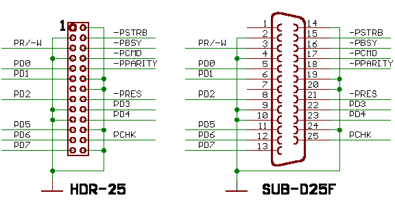
ProFile has a female Sub-D25 connector, while the Widgets use a 26pin header. The pinout of both connector variants is the same. Build a cable with two pin headers to test Widgets, and a second one with one header and a crimped Sub-D25 male connector for the ProFiles. The outermost wire (pin 26) is not used with the Sub-D25 connector and can be removed. These cables should not be longer than necessary. 50cm is good, up to a meter should work.
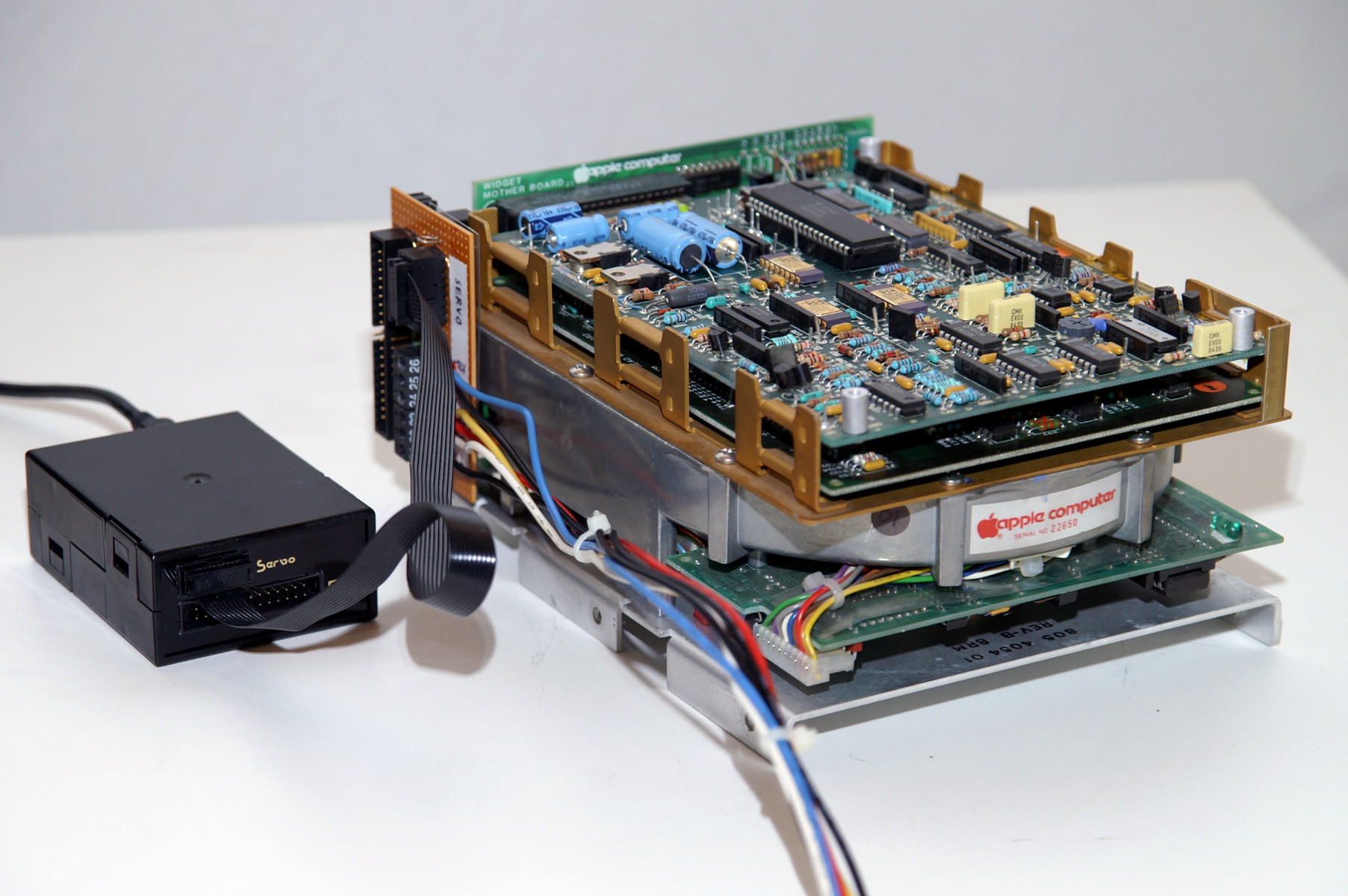
Connecting to the servo board is more difficult. UsbWidEx is attached directly to the card edge connector of the Widget motherboard, and you have to provide power to the drive as well. In a similar way, the Nisha and RO522 drives used inside the Macintosh HD20 can be accessed, too.
| signal | from servo connector pin | to Widget Motherboard pin | to Nisha / Rodime pin |
|---|---|---|---|
| ServoIn | 3 (TxD output) | 19 | 17 |
| ServoOut | 5 (RxD input) | 17 | 15 |
| ServoErr | 7 (input) | 26 | 23 |
| ServoRdy | 9 (input) | 22 | 21 |
| SioRdy | 6 (input) | 21 | 19 |
| -ServoRst | 8 (output) | 28 | 18 |
| Gnd | 1 and 10 | 2..20 (all even pins), 40 | 2, 4, 6, 26 |
| +5 V | 35, 36, 37, 38 | 8, 10 | |
| +12 V | 33, 34 | 20, 22 | |
| -12 V | 31, 32 | 24 | |
| +12 V for motor | 39 | 25 |
You can use the same power supply for analog +12 V and motor supply, but use separate cables and connect them at the power supply.
Note: To keep the drive heads from moving around during transport, the actuator gets blocked by a solenoid brake when power is removed. Issue a servo reset pulse after the drive has come to full speed (after approximately 20 seconds) to release the HDA brake. When debugging is finished, park the heads before turning off the power! This ensures the brake will clamp them in the correct position.
 |
 |
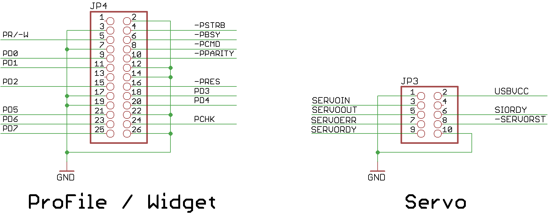
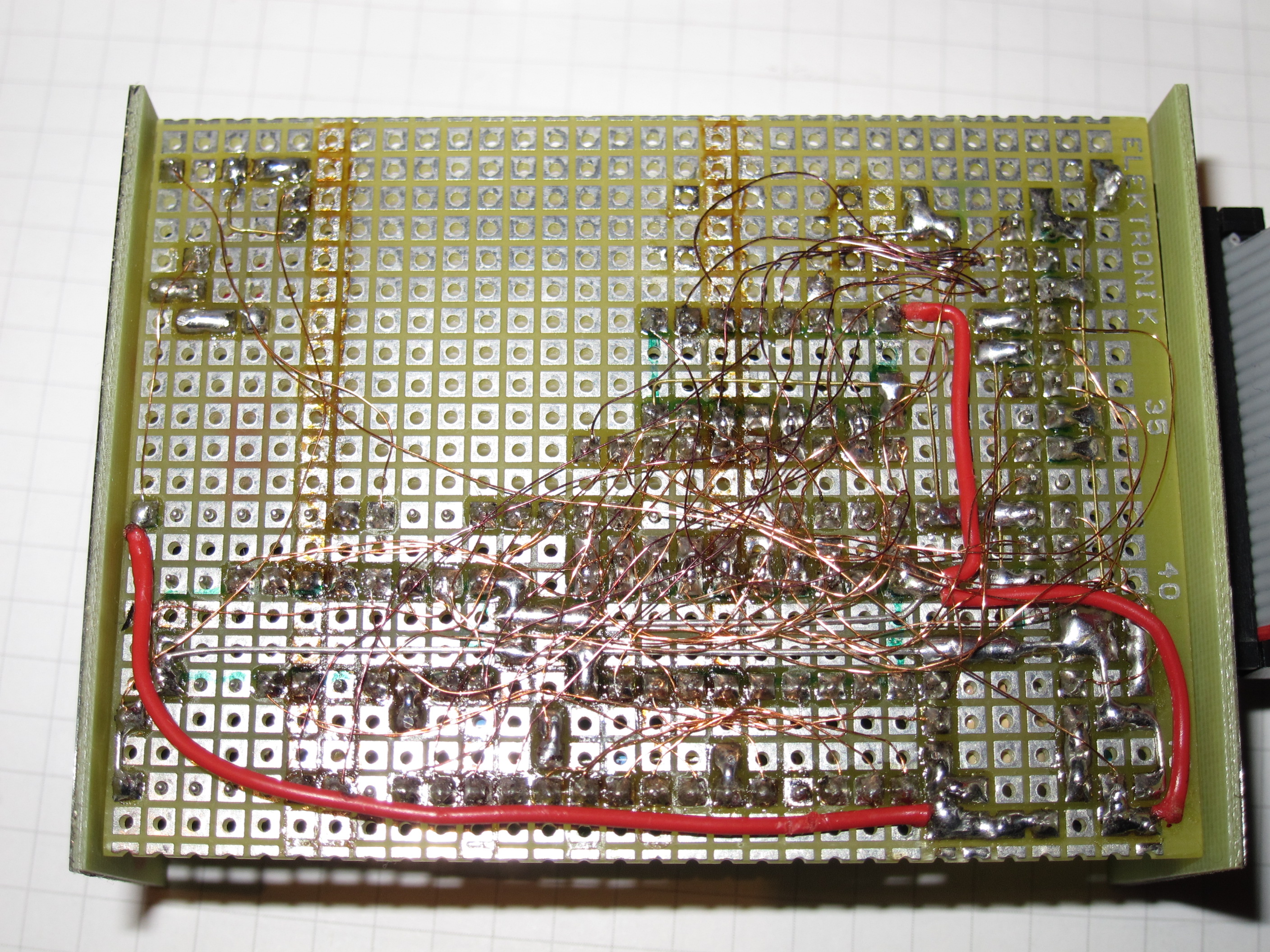
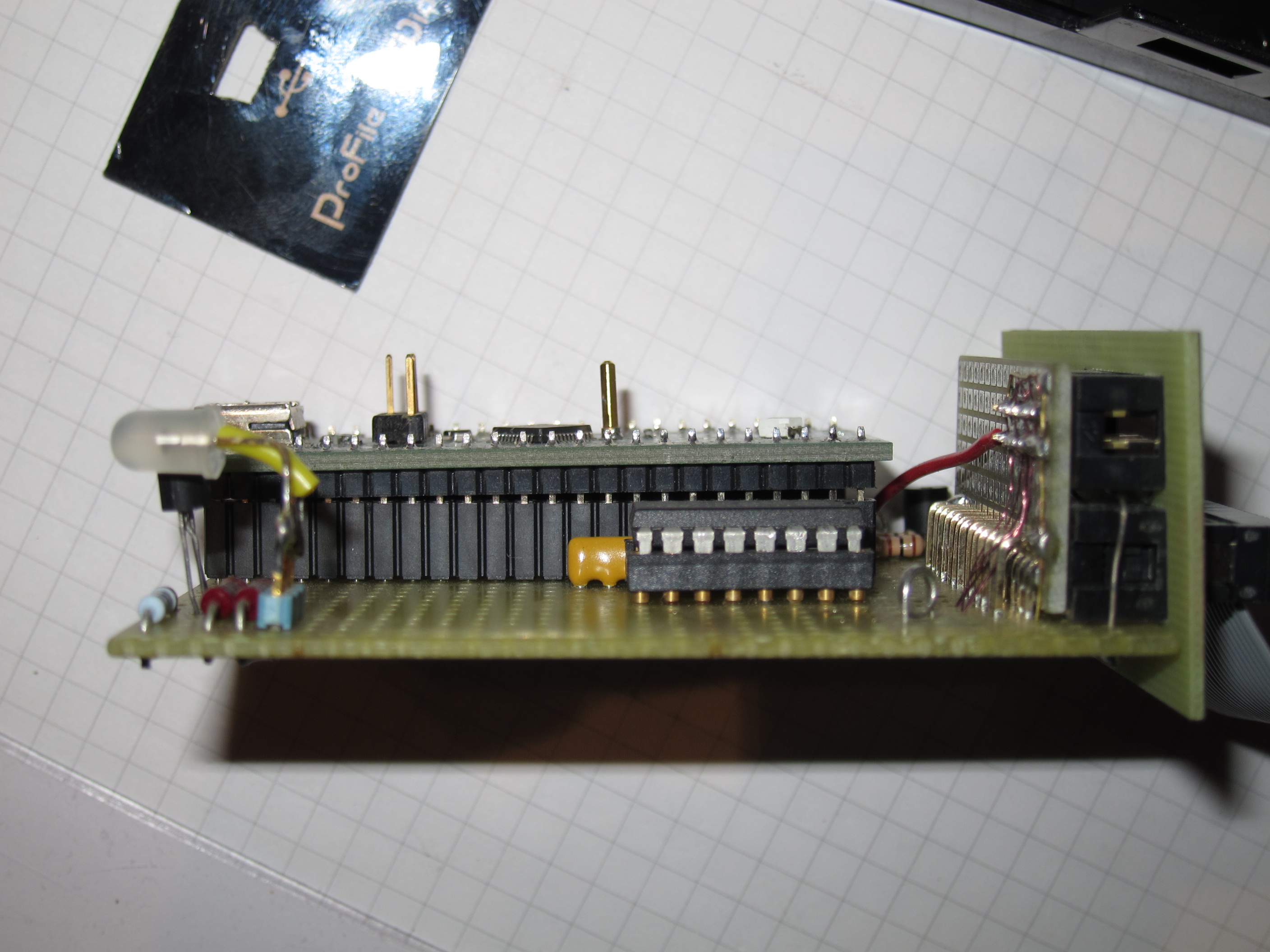
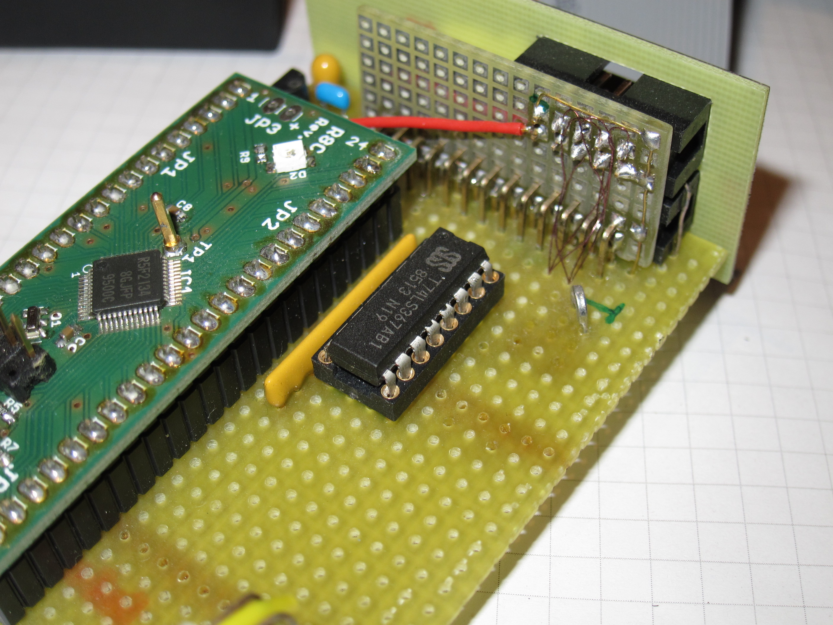
The hardware consists of two parts: a generic PCB with the R8C microcontroller and USB interface, and a piece of breadboard that holds the remaining components. As speed does not matter here, the whole interface protocol is carried out in software. All lines from the ProFile connector are buffered and routed to microcontroller pins. This results in a very simple schematic (click on the image for a pdf version):
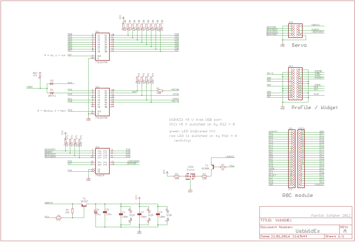
A 74LS245 bus driver is used to buffer the data bus PD0..7, which is driven by the R8C/34 port P0. These lines are bi-directional, therefore their direction can be set with pin P6.7. A second 74LS245 driver is used for the status signals. Except for /PBsy all these signals are generated by the host. Their direction can be swapped to emulate a device (by setting pin P1.3 low), but this is not used at the moment.
The servo interface has two output and four input lines, therefore a 74LS367 is used as a buffer. These parts can be substituted with almost anything that is able to drive a couple of TTL loads. However, classic 'LS are recommended here because they are more robust against ESD, latchup and other misuse than their modern 'HCT or 'LVC counterparts.
UsbWidEx is a bus-powered USB 2.0 device. It has to ask the host computer for permission before drawing more than 100 mA from the USB connector. Today nobody cares about this, but this is what the spec says. Therefore the I/O buffers can be disabled by the microcontroller. They are off when P1.2 high or open.
Finally, there is a two-color indicator lamp that glows green when the I/O power is applied, and red when P1.6 is set low.
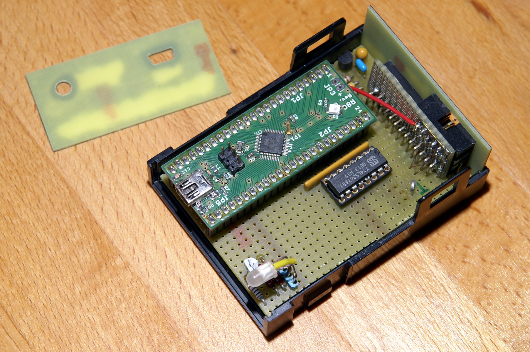
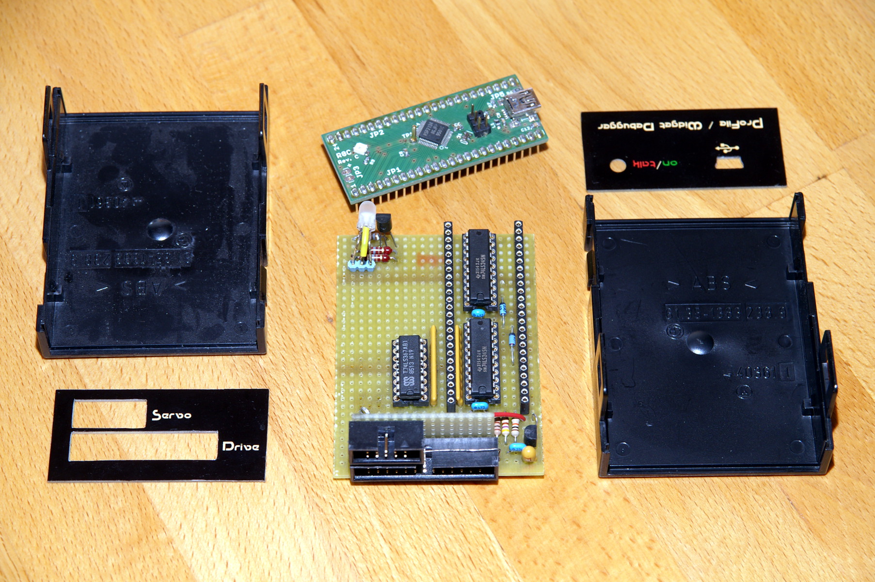
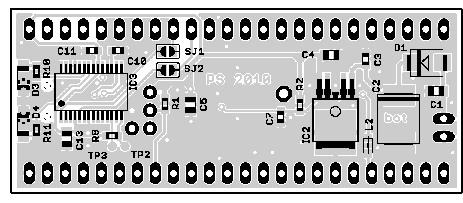
The most magic part of the circuit is in the bottom right of the schematic: the R8C module. This is a small PCB that holds a Renesas R8C/34 microcontroller (R5F21348GJFP or similar type) with its associated components and a FTDI232R USB-to-UART bridge. Here is the schematic diagram of this module. The pictures below give some impression of the mechanical construction.
 |
 |
To implement the firmware, the KPIT GNUM16C v11.01 Windows Tool Chain has been used. KPIT has dropped the support for the M16C/R8C family, but the compiler is still available in their toolchain archive section.
I have designed UsbWidEx because I needed a tool to troubleshoot my non-working drives. It has been revised many times, and one after another all necessary functions have been added. It may still change in the future, in case I dislike anything or require something new. For many years, everything I knew about ProFile and Widget was based on firmware disassembly and reverse engineering. This yielded enough information to design IDEfile in 2004. Recently, a lot of documents from Apple's disk group have appeared. These have been scanned and can be viewed at bitsavers.org. This bunch of information helped me to correct and complete the command set.
UsbWidEx is no commercial product and I do not provide any kits or assembled modules. However, its hardware is no rocket science and someone capable of SMD soldering should be able to build his (or her) own. Partlists, schematic diagram and the firmware code file can be downloaded below.
a) generic Renesas R8C module:
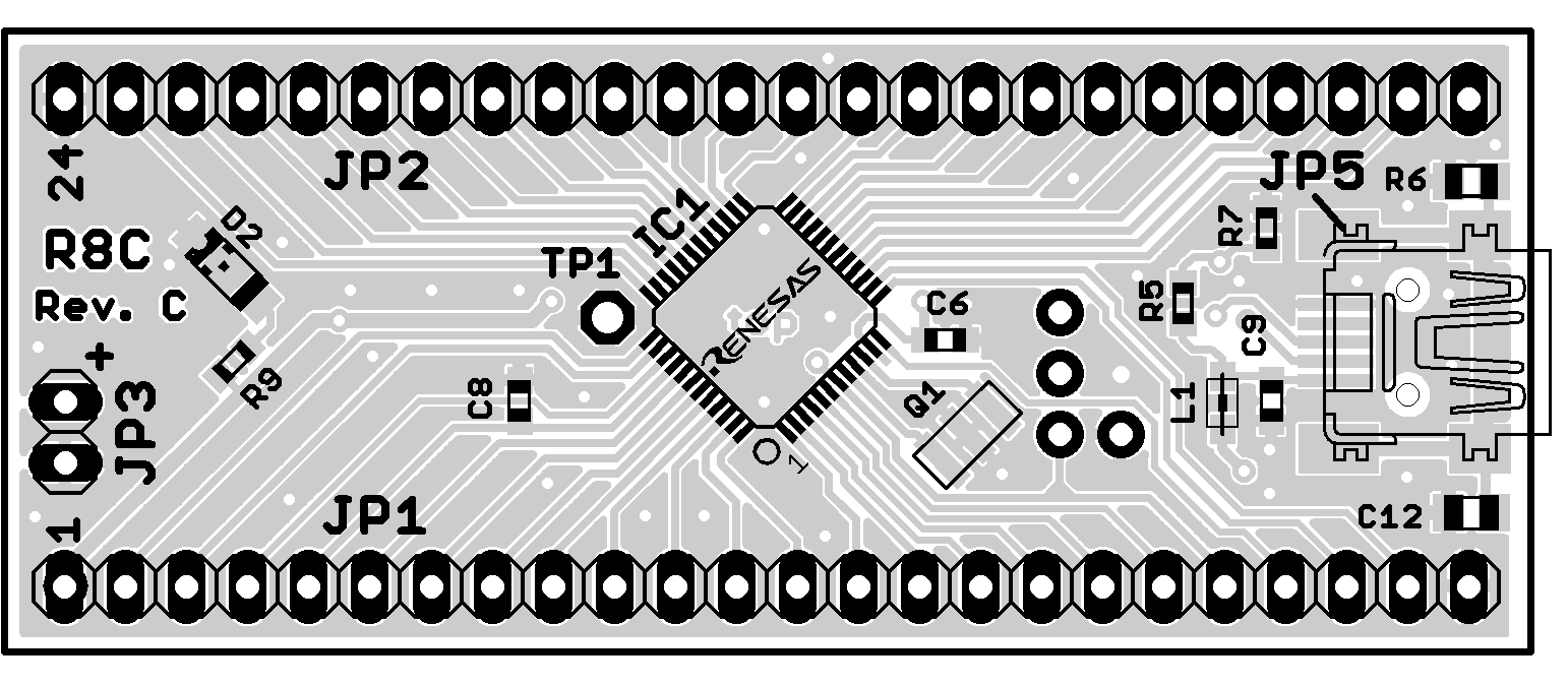
For UsbWidEx, the R8C module is operated in host-powered mode. Power is supplied from the USB port, which means L1 has to be fitted. Voltage regulator IC2 and its surrounding components are not required. Use an 18.432 MHz resonator.
b) the UsbWidEx-specific periphery:
 |
 |
 |
Having assembled the R8C module, first make sure that the USB bridge is working. Open the solder jumpers SJ1 and SJ2 and short pin 1 of SJ1 to pin 1 of SJ2. This connects RxD of the FTDI chipto TxD so that everything you type in the terminal window on your PC is looped back. Install the Virtual Com Port Driver from the FTDI website and connect the R8C module to your PC. In your system settings, you should see a new COM port. Open a terminal window and select this port. Set the communication parameters to 57k6, 8 data bits, 1 or 2 stop bits, no parity. Turn local echo off. Type some text to check if this is working properly. Then remove the short on the R8C board and close both solder jumpers. Now the microcontroller is connected to your serial port.
Use the Renesas Flash Development Toolkit (FDT) software to program the microcontroller. The current version is 4.09, later ones should work, too. Download it from the Reneas website and install the package. Close your terminal program and start the FDT Basic tool.
Select "new settings" from the menu. In the device selection dialog, enter "r5f21348e" (or which type you are using). Select the device and click "next". Select UsbWidEx' COM port and click "next". Remove the check mark at "Use Default" and select a speed of 115200. Click "next". Check "Readback Verification" and click "finish".
Now disconnect the USB cable and short the pins "MODE" and "Gnd" at the programming connector JP4. Reconnect the board. In the FDT window, check "User/Data Area" and select the file with the UsbWidEx firmware:
Click "Program Flash" to load the firmware into the microcontroller. Exit FDT and disconnect the USB cable. Remove the short from the programming connector.
If you own a Renesas E8a debugger, you can use this to flash the firmware -- it is significantly faster than the serial bootstrap mode.
Reconnect the USB cable and start your terminal program (remember: 57600-8-1). The two-color LED on the UsbWidEx board should glow red. Open the COM port and press any key on the terminal window. The LED should turn off and a signon message should appear:
UsbWidEx --- ProFile/Widget Debugger V1.02
 (c) Patrick Schaefer, 2012-14

  1 - Backup drive to file
  2 - Restore drive from file
  3 - Low-level format
  4 - Surface scan
  5 - ProFile 5M debugger
  6 - ProFile 10M debugger
  7 - Widget controller debugger
  8 - Widget servo debugger
  9 - Interface line test

Select function:
Now press "9" to select the Interface line test and check all pins of the ProFile Bus and Servo connectors.
UsbWidEx uses a FTDI FTDI232R serial-to-USB bridge chip, so from the host computer's point of view it looks like a serial port and gets a COM number assigned (e.g. COM8). Start your favourite terminal program (for Windows TeraTerm works fine), the RS-232 settings are 57600-8-1, no handshake.
Press any key to get the main menu:
UsbWidEx --- ProFile/Widget Debugger V1.02
 (c) Patrick Schaefer, 2012-14

  1 - Backup drive to file
  2 - Restore drive from file
  3 - Low-level format
  4 - Surface scan
  5 - ProFile 5M debugger
  6 - ProFile 10M debugger
  7 - Widget controller debugger
  8 - Widget servo debugger
  9 - Interface line test

Select function:
Type the appropriate number to select a function.
----> Here is a command reference sheet with a summary for daily use.
This function allows you to create a backup file on your PC from a ProFile drive connected to UsbWidEx. There are three options than can be selected:
1024 (vs. 532) bytes per block? Use 1024 ("Y") to get an image that is compatible to the raw data contained in an IDEfile volume. Use 532 ("N") for further processing with BLU or LISAem.
BLU header in first block? Select this ("Y") to get a BLU compatible header into the first block of the image file. This header consists of the contents of block 0xFFFFFF (the spare table) followed by a creator message "UsbWidEx V1.02 "
Apply 5:1 interleave? If selected ("Y"), the ProFile blocks are shuffled in a 5:1 order before written into the image file. This is to maintain compatibility with BLU, moreover there is no real use for it.
Image block number 	0,  1,  2,  3,  4,  5,  6,  7,  8,  9, 10, 11, 12, 13, 14, 15
ProFile block number	0,  5, 10, 15,  4,  9, 14,  3,  8, 13,  2,  7, 12,  1,  6, 11
To create an image that can be copied directly into an IDEfile volume, select options "YNN". To get a BLU file, select "NYN" for a Widget and "NYY" for a ProFile.
UsbWidEx now reads each block from the drive and sends it to the host PC using the XMODEM protocol (128 byte records, checksum and CRC supported). This takes around 57 minutes for a 5 MB volume sent with 1024 bytes per block. The resulting file sizes are:
| 5 MB volume | 10 MB volume | |
|---|---|---|
| 532 byte/block | 5 175 296 (0:30) | 10 350 592 (1:03) |
| with BLU header | 5 175 828 | 10 351 656 |
| 1024 byte/block | 9 961 472 (0:57) | 19 922 944 (1:55) |
| with BLU header | 9 962 496 | 19 924 992 |
In case a block is unreadable, it is replaced by a dummy block. This consists of the block number (in hex), a message "THIS BLOCK WAS UNREADABLE ", and is padded with spaces (0x20). Of course, before a block is considered unreadable a couple of retries are done.
After the transfer is completed, the number of faults is reported.
Use this to write an image file on your PC back to a ProFile drive connected to UsbWidEx. You have to specify the image format -- 1024 or 532 bytes, BLU header or not, 5:1 interleaving or not. In case you don't remember the image settings, use a hex editor (like HxD) to look into the file. If the first line starts with "PROFILE" or "WIDGET", this is likely to be a BLU header. Otherwise there might be an "AAAA" signature in the first line, which identifies a Lisa boot block, Now look where the next block starts: at 0x214 or at 0x400. This gives you the block size -- 532 or 1024 bytes.
Now the image file has to be sent in XMODEM format (128 bytes per record, Checksum or CRC). In case the file is smaller than the drive capacity, only the blocks given in the file are written. The rest of the drive remains unchanged. If the image is bigger than the drive, everything after the last useable block is ignored.
During low-level format, initial data structures are generated on the magnetic disks. All tracks are erased, sector marks and headers are written, and all blocks are filled with a test pattern. After that, a surface scan is done and the spare tables for bad block management are initialized.
Note: I do not own a ProFile 10M, therefore this LLF procedure has not been tested yet. It has been implemented according to my disassembly of the P10LLF firmware revision D6.06.
The drive type is detected automatically and the appropriate algorithm is chosen. ProFile drives require diagnostic firmware to be fitted. For the ProFile 5M algorithm, P5LLF revision D3.11 is required, ProFile 10M needs P10LLF rev. D6.06. Other revisions may work but have not been tested. Widgets can be formatted with their stock firmware. The latest revision 1-A.4.5 (341-0289-D) is recommended.
After formatting, re-install the R/W firmware and run the read/write/read test a few times. This will detect any bad blocks and let the drive enter them into its spare table.
Four different tests are provided:
linear read test. Reads each block, one after another. During reading, ProFile checks its internal CRC. If there is a mismatch, the block is re-read 100 times. If more than 20% of these reads fail, the block is rewritten. If rewriting fails, the block is spared. In case all of these 100 retries fail, up to another 90 retries are made. A block that cannot be recovered within these 191 attempts is entered into the Bad Block table.
butterfly read test. Reads each block, but alternately one track from the center and one from the perimeter of the drive. This test puts more stress on the head positioning mechanim than the linear read test.
read/write/read test. Reads each block, then overwrites each block with a test pattern and CRC, then re-reads each block and check for CRC match. The first run gives an overview about the current status of the drive. Weak (status 08) or bad (status 09) blocks are listed and bad blocks are entered into the Bad Block table. In the second run, all blocks are filled with a 55 5A AA test pattern and a CRC. ProFile will automatically spare all blocks with media defects or damaged headers. If you see too many faults in this run, abort here and low-level format the drive. The last run reads back all blocks and checks the previously written CRC. You should not see any errors here. In case you do, there might be a weak block. Re-run this test. A large number of faults in the last run (or after the R/W/R test has been repeated a couple of times) indicate a defective analog board or contamination inside the HDA assembly. CRC errors indicate a defective controller board or a bad (or too long) cable. The two resistor networks at position U1, U2 on the controller board should be 100 Ohm. Not 47 Ohm and not 470.
This test will destroy any existing data on the drive.
zero all blocks. Fills each block with 532 zeros. This test will destroy any existing data on the drive.
During the tests, press any key to abort.
From this menu you can read single blocks from your drive, modify their contents, and write them back. Besides that, diagnostic commands could be sent to a 5MB Profile with diagnostic firmware installed. ProFile 10M has a different diagnostic command set, so use the 10M ProFile Debugger for these drives.
Note that all parameter values have to be given as hex numbers. Leading zeros may be skipped, but parameters which are not separated by a comma have to be specified with the required number of digits. E.g. "r xxxx,rrtt" with xxxx = 0x002E, rr = 0x64 and tt = 1 has to be written as "r 2E,6401".
a, b: --
c: send a generic ProFile command. Enter the command bytes and press <CR> after the last one. You will be asked if the drive returns data. In that case, 532 bytes are transferred into the data buffer.
d: dump command and data buffer. The command buffer is 16 bytes long. It is used for the commands to be sent to the drive, and for the command completion status received from there. So after most commands the first four bytes contain the response from the last operation.
The 532 byte data buffer holds the data received from a read command. This data is transferred to the drive during a write operation.
e xxxx,yy: enter yy into the data buffer at adress xxxx. Use this to modify single bytes. You do not want to install LisOS this way, do you?
f: format drive. Jumper P7 between U23 and U24 has to be closed to allow the Z8 to erase all tracks, write sector marks, write headers and fill all blocks with a D6B9 pattern. Remove the jumper after formatting has finished! Status byte 4 holds the number of errors occurred, and the data buffer contains a list of error code for the first 32 faulty blocks. Each error code consists of four bytes: cylinder, head, sector, and fault type. The fault type has the same format as status byte 3. This command requires a diagnostic Z8 and takes about 3 minutes.
g: get drive info. This reads the spare table (block 0xFFFFFF) and decodes its contents.
h: display the help text. So does '?'.
i: initialize Profile spare table. Tells ProFile to fill cylinder 77 / head 2+3 / sector 0..15 with a spare table template. Status byte 4 holds the number of sectors that could not be written, and the data buffer contains a list of error codes for each faulty sector. Each error code consists of one byte, where the lower 4 bits are the sector number (0..F) and bit 4 is zero for head 2 or one for head 3. The upper three bits indicate the fault type. The format of these bits is the same as usually for status byte 3. This command requires a diagnostic Z8.
j n: select IDEfile volume n. Without a parameter, the currently selected volume is reported. Of couse this command works only with an IDEfile drive.
k: --
l: toggle trace mode off/on. Usually UsbWidEx displays the command bytes sent to and the status bytes received from the drive, which looks like this: "000000006414 --> 00000000". Sometimes you don't want this (e.g. when controlling UsbWidEx via LabView), so you can turn it off. 'l' could also be used together with a parameter: "l 0" turns the trace mode off, "l 1" turns it on.
Results and error messages are not affected by the trace mode flag.
m xxxx: read 512 bytes from ProFile RAM starting at address xxxx into buffer. ProFile has 1kB, so you need two passes to get all -- "m0" + "m200". This command requires a diagnostic Z8.
n xxxx: write buffer into ProFile RAM starting at address xxxx. This may totally screw up your drive, so use it only in a read-modify-writeback way! This command requires a diagnostic Z8.
o: --
p: turn off stepper motor. Rotate stepper fully counterclockwise for parking position. This command requires a diagnostic Z8.
q: quit to main menu.
r xxxx,rrtt: read block xxxx into the data buffer. You can specify retry count rr and sparing threshold tt, otherwise the default values 0x64 (100 retries) and 0x24 (36%) are used. Once given, the values are remembered for further Read/Write/WriteVerify operations. This command works with any ProFile compatible drive -- ProFile, Widget, IDEfile, X/Profile or SUN.
s xxxx: replace block xxxx with a spare block. This command requires the R/W firmware.
t cchhnn: read the nn'th sector on cylinder cc, head hh including its header. Due to the 5:1 sector interleaving, the nn'th sector after the index mark is not sector number nn. Here is the translation table:
position after index	0  1  2  3  4  5  6  7  8  9  A  B  C  D  E  F
sector on head 0	0  D  A  7  4  1  E  B  8  5  2  F  C  9  6  3
sector on head 1	3  0  D  A  7  4  1  E  B  8  5  2  F  C  9  6
sector on head 2	6  3  0  D  A  7  4  1  E  B  8  5  2  F  C  9
sector on head 3	9  6  3  0  D  A  7  4  1  E  B  8  5  2  F  C
This command requires a diagnostic Z8.
u: --
v xxxx,rrtt: verify-write the data buffer into block xxxx. You can specify retry count rr and sparing threshold tt, otherwise the default values 0x64 (100 retries) and 0x24 (36%) are used. Once given, the values are remembered for further Read/Write/WriteVerify operations. This command works with any ProFile compatible drive -- ProFile, Widget, IDEfile, X/Profile or SUN.
w xxxx: write data buffer into block xxxx. This command works with any ProFile compatible drive -- ProFile, Widget, IDEfile, X/Profile or SUN.
x xxxx,rrtt: continuously read block xxxx into data buffer. Press any key to terminate.
y xxxx: continuously write data buffer into block xxxx. Press any key to terminate. Be careful with this command when auto-increment is enabled -- it will overwrite your whole drive!
z: scan Profile for defects. Status byte 4 holds the number of errors occurred, and the data buffer contains a list of error code for the first 32 faulty blocks. Each error code consists of four bytes: cylinder, head, sector, and fault type. The fault type has the same format as status byte 3. No sparing occurs, the bad sectors are just reported.
To calculate the block number (LBA) required by the R/W firmware from the cylinder/head sector address used by the diagnostic firmware, apply the following formula:
 LBA = 64* cylinder + 16* head + sector       for cylinder <77 (04Dh),
 LBA = 64* (cylinder-1) + 16* head + sector   for cylinder >77
Cylinder 77 (the spares track) is used internally only and cannot be accessed via read/write commands. This command requires a diagnostic Z8.
!: output a /PReset pulse: This sends a hardware reset to the drive, using the /PReset line.
+: enable auto-increment mode. Block number is incremented after each Read/Write/WriteVerify operation. With auto-increment enabled, the 'y' command will overwrite the whole drive.
-: disable auto-increment mode.
From this menu you can send diagnostic commands to a 10MB ProFile. ProFile 10M has a completely different diagnostic command set, therefore these commands will not work with a 5MB unit.
Note that all parameter values have to be given as hex numbers. Leading zeros may be skipped, but parameters which are not separated by a comma have to be specified with the required number of digits. E.g. "r xxxx,rrtt" with xxxx = 0x002E, rr = 0x064 and tt = 0x01 has to be written as "r 2E,6401".
a, b: --
c: send a generic ProFile command. Enter the command bytes and press <CR> after the last one. The checksum is added automatically. You will be asked if the drive returns data. In that case, 532 bytes are transferred into the data buffer.
d: dump command and data buffer. The command buffer is 16 bytes long. It is used for the commands to be sent to the drive, and for the command completion status received from there. So after most commands the first four bytes contain the response from the last operation.
The 532 byte data buffer holds the data received from a read command. This data is transferred to the drive during a write operation.
e xxxx,yy: enter yy into the data buffer at adress xxxx. Use this to modify single bytes. You do not want to install LisOS this way, do you?
f: format current track. Jumper P7 between U23 and U24 has to be closed to allow the Z8 to erase the current track, write sector marks, write headers and fill all blocks with a D6B9 pattern. Remove the jumper after formatting has finished! Status byte 4 holds the number of errors occurred, and the data buffer contains a list of error code for the first 32 faulty blocks. Each error code consists of four bytes: cylinderHi, cylinderLo, head/sector, and fault type. The fault type has the same format as status byte 3.
g: get drive info. This reads the spare table (block 0xFFFFFF) and decodes its contents.
h: display the help text. So does '?'.
i: initialize Profile spare table. Tells ProFile to fill cylinder 153 / head 2+3 / sector 0..15 with a spare table template. Status byte 4 holds the number of sectors that could not be written, and the data buffer contains a list of error codes for each faulty sector. Each error code consists of one byte, where the lower 4 bits are the sector number (0..F) and bit 4 is zero for head 2 or one for head 3. The upper three bits indicate the fault type. The format of these bits is the same as usually for status byte 3.
j n: select IDEfile volume n. Without a parameter, the currently selected volume is reported. Of couse this command works only with an IDEfile drive.
k ccc,hx: seek to cylinder ccc / head h. If x=0, a regular seek is done, i.e. after reaching the target track, three consecutive headers are read to confirm proper positioning. With n=1 a diagnostic seek is done. Here the heads are moved without trying to read any data from the disk surface. Use the diagnostic seek together with the format track command.
l: toggle trace mode off/on. Usually UsbWidEx displays the command bytes sent to and the status bytes received from the drive, which looks like this: "000000006414 --> 00000000". Sometimes you don't want this (e.g. when controlling UsbWidEx via LabView), so you can turn it off. 'l' could also be used together with a parameter: "l 0" turns the trace mode off, "l 1" turns it on.
Results and error messages are not affected by the trace mode flag.
m: test controller RAM. If the test passes, status byte 1 is zero. In case of a fault, the data buffer contains MSB and LSB of the bad RAM address, its expected contents and the data read back.
n, o: --
p x: park heads. With a parameter x<>0 given, the stepper motor is switched off but the heads are not moved.
q: quit to main menu.
r ccc,hs: read cylinder ccc / head h / sector s into the data buffer. Once given, the values are remembered for further Read/Write/WriteVerify operations.
s: get format result table
t ccc,hn: read the n'th sector on cylinder ccc, head h including its header. Due to the 5:1 sector interleaving, the nn'th sector after the index mark is not sector number n. Here is the translation table:
position after index	0  1  2  3  4  5  6  7  8  9  A  B  C  D  E  F
sector on head 0	0  D  A  7  4  1  E  B  8  5  2  F  C  9  6  3
sector on head 1	3  0  D  A  7  4  1  E  B  8  5  2  F  C  9  6
sector on head 2	6  3  0  D  A  7  4  1  E  B  8  5  2  F  C  9
sector on head 3	9  6  3  0  D  A  7  4  1  E  B  8  5  2  F  C
u, v: --
w ccc,hs: write data buffer into cylinder ccc / head h / sector s. Once given, the values are remembered for further Read/Write/WriteVerify operations.
x ccc,hs: continuously read cylinder ccc / head h / sector s into data buffer. Press any key to terminate.
y ccc,hs: continuously write data buffer into cylinder ccc / head h / sector s. Press any key to terminate. Be careful with this command when auto-increment is enabled -- it will overwrite your whole drive!
z: scan Profile for defects. Status byte 4 holds the number of errors occurred, and the data buffer contains a list of error code for the first 32 faulty blocks. Each error code consists of four bytes: cylinderHi, cylinderLo, head/sector, and fault type. The fault type has the same format as status byte 3. No sparing occurs, the bad sectors are just reported.
To calculate the block number (LBA) required by the R/W firmware from the cylinder/head sector address used by the diagnostic firmware, apply the following formula:
 LBA = 64* cylinder + 16* head + sector       for cylinder <153 (099h),
 LBA = 64* (cylinder-1) + 16* head + sector   for cylinder >153
Cylinder 153 (the spares track) is used internally only and cannot be accessed via read/write commands.
!: output a /PReset pulse: This sends a hardware reset to the drive, using the /PReset line.
+: enable auto-increment mode. Cylinder/head/sector is incremented after each Read/Write operation and cylinder/head is incremented after each seek. With auto-increment enabled, the "y" command will overwrite the whole drive.
-: disable auto-increment mode.
From this menu you can read single blocks from your drive, modify their contents, and write them back. Besides that, diagnostic commands could be sent to a Widget. UsbWidEx talks to the controller board, which controls the R/W electronics and the servo system inside the drive.
Note that all parameter values have to be given as hex numbers. Leading zeros may be skipped, but parameters which are not separated by a comma have to be specified with the required number of digits. E.g. "r xxxx,rrtt" with xxxx = 0x002E, rr = 0x064 and tt = 0x01 has to be written as "r 2E,6401".
a: auto adjust track offset. The ATF DAC value is returned (in decimal).
b x: set recovery off for x=0 (default), or on for x=1
c: send a generic Widget command. Enter the command bytes and press <CR> after the last one. The checksum is added automatically. You will be asked if the drive returns data. In that case, 532 bytes are transferred into the data buffer.
d: dump command and data buffer. The command buffer is 16 bytes long. It is used for the commands to be sent to the drive, and for the command completion status received from there. So after most commands the first four bytes contain the response from the last operation.
The 532 byte data buffer holds the data received from a read command. This data is transferred to the drive during a write operation.
e xxxx,yy: enter yy into the data buffer at adress xxxx. Use this to modify single bytes. You do not want to install LisOS this way, do you?
f o,i: format current Widget track with a given offset and interleave. Offset means the number of physical sectors between the index mark and logical sector 0. Default value is 0. For the interleave, 1:1 to 1:7 could be chosen (see table below). Default value is 1 (1:2). Both values are remembered after you have entered them the first time, and are used as new defaults.
Set  I'leave  Index   2    3    4    5    6    7    8    9   10   11   12   13   14   15   16   17   18   19
-------------------------------------------------------------------------------------------------------------
0     1:1	0     1    2    3    4    5    6    7    8    9   10   11   12   13   14   15   16   17   18
1     1:2	0    10    1   11    2   12    3   13    4   14    5   15    6   16    7   17    8   18    9
2     1:3	0    13    7    1   14    8    2   15    9    3   16   10    4   17   11    5   18   12    6
3     1:4	0     5   10   15    1    6   11   16    2    7   12   17    3    8   13   18    4    9   14
4     1:5	0     4    8   12   16    1    5    9   13   17    2    6   10   14   18    3    7   11   15
5     1:6	0    16   13   10    7    4    1   17   14   11    8    5    2   18   15   12    9    6    3
6     1:7	0    11    3   14    6   17    9    1   12    4   15    7   18   10    2   13    5   16    8
		(this is the physical order of the sectors on disk)
Offset and interleave set number could be looked up at offset 0x08 and 0x09 in the spare table.
g: get drive info. This reads ID block and spare table and decodes its contents.
Note: a Widget has 76 spare blocks, a ProFile has 32. You don't have to worry if up to 25% of them are used, this is still acceptable for a healthy drive. Emulators like IDEfile or X/ProFile rely on the media's wear levelling, so they should never indicate any spared blocks.
h: display the help text. So does '?'.
i o,i: initialize Widget spare table with a given offset and interleave. These values have to be the same as used for formatting, and they are remembered from there.
j n: select IDEfile volume n. Without a parameter, the currently selected volume is reported. Of couse this command works only with an IDEfile drive.
k cccc,hss: seek Widget's head to a given cylinder/head/sector. If only the cylinder has been specified, head 0 and sector 0 are assumed. If no parameters are given at all, the last ones are used again. You have to seek to the desired block before using the Diagnostic Read or Write command.
Note that head and sector have to be specified together, like "103" for head 1, sector 3. Widget-10 has 514 tracks (0000..0201), 2 heads (00..01) and 19 sectors (00..12). 76 of the total of 19532 blocks are used as spares (0..4B), leaving 19456 blocks (LBA 0000..4BFF) to the user.
How to calculate cylinder, head, sector from the logical block number:
Widget-10 has 76 (0x4C) spare blocks which are occupy each 256th physical block. These have to be skipped during LBA to CHS conversion. This results in a physical block number (PBA). For a block that has not been spared, it is calculated from
	PhysicalBlockNumber := LogicalBlockNumber + LogicalBlockNumber/256
	IF (LogicalBlockNumber mod 256 + (LogicalBlockNumber/256) mod 256 > 255)
	   THEN PhysicalBlockNumber := PhysicalBlockNumber +1
In case a block has been replaced by a spare, i.e. its logical block number has been found in the spare table, its PBA is just
PhysicalBlockNumber := (spare number +1) * 256Now, from this PBA the CHS values can be calculated:
	LogCylinder := PhysicalBlock / (Heads*Sectors)
	Temp := PhysicalBlock mod (Heads*Sectors)
	LogHead := Temp / Sectors
	LogSector := Temp mod Sectors
Logical cylinder and head correspond to the physical ones, but for the sector a remapping is applied. The spare table contains an interleave map at offset 0x1C6..0x1D8, which translates the logical sector into a physical sector number. This is where you have to seek to. This interleave map must not be confused with the interleave set specified during formatting. During formatting the order of the physical sectors on disk is defined, while the interleave map describes the correlation between logical and physical sectors. The default map table is
block number	0    1    2    3    4    5    6    7    8    9   10   11   12   13   14   15   16   17   18
sector number	0   12    5   17   10    3   15    8    1   13    6   18   11    4   16    9    2   14    7
together with interleave set 1 (1:2) this yields an 1:5 interleaving of the logical blocks on the disk.
       Index   2    3    4    5    6    7    8    9   10   11   12   13   14   15   16   17   18   19
------------------------------------------------------------------------------------------------------
sector	  0   10    1   11    2   12    3   13    4   14    5   15    6   16    7   17    8   18    9
 (hex)   00   0A   01   0B   02   0C   03   0D   04   0E   05   0F   06   10   07   11   08   12   09
logical	  0    4    8   12   16    1    5    9   13   17    2    6   10   14   18    3    7   11   15
 (hex)   00   04   08   0C   10   01   05   09   0D   11   02   06   0A   0E   12   03   07   0B   0F


	PhySector := (LogSector * 12) mod 19
So the logical block number 5 (i.e. the 6th one on this track) is stored into sector number 3, which is the 7th one counted from the falling edge of the Index pulse.
l: toggle trace mode off/on. Usually UsbWidEx displays the command bytes sent to and the status bytes received from the drive, which looks like this: "000000006414 --> 00000000". Sometimes you don't want this (e.g. when controlling UsbWidEx via LabView), so you can turn it off. 'l' could also be used together with a parameter: "l 0" turns the trace mode off, "l 1" turns it on.
Results and error messages are not affected by the trace mode flag.
m: read Widget spare table into the data buffer.
There are two copies of the spare table which can be located at any of the 76 spare blocks. Usually they occupy spare number 0x19 and 0x32, but in case one of these blocks is bad, other spares can be used as substitutes. To read the spare table sector manually, enter "k af,f" for spare 0x19 or "k 157,111" for spare 0x32 followed by "x". "x" will continuously read the same block, press any key to stop this.
n: write data buffer into Widget spare table. Anything might happen if the buffer does not contain a valid spare table structure.
o xx: list all tracks whose ATF offset is above the given value. Default xx=0x10.
p: park heads: move the heads onto track 565 (0x235), close to the inner endstop. Issue this command before powerdown in case the drive will be shipped.
q: quit to main menu.
r xxxx,rrtt: read block xxxx into the data buffer. You can specify retry count rr and sparing threshold tt, otherwise the default values 0x64 (100 retries) and 0x24 (36%) are used. Once given, the values are remembered for further Read/WriteVerify operations. This command works with any ProFile compatible drive -- ProFile, Widget, IDEfile, X/Profile or SUN.
s n,x: read Widget status register n (0=controller, 1=servo, 2=abort). Controller and Servo status consist of eight blocks with four bytes each. When reading the Servo status, the regular command completion status from the controller is sent as well, so only the last four bytes in each line are important. The Abort status is 16 bytes long, again preceeded by 4 bytes command completion status. For n=0 (controller status), setting x=1 gives a description of the status bits.
With no parameter given, 's' returns the Controller status.
t nn: diag read sector nn including header into data buffer. You have to seek to the desired cylinder / head first. Interleaving is applied, but LBA mapping is not. So for a drive formatted with 1:2 interleave (default) "t 2" will return sector number 2 of the current track, which is the 5th one after Index.
u x: recalibrate to track 505 (0x1F9) if x=0 or track 544 (0x220) if x=1. Track 505 is the regular (data) recal position, track 544 is used as reference during formatting.
v xxxx,rrtt: verify-write the data buffer into block xxxx. You can specify retry count rr and sparing threshold tt, otherwise the default values 0x64 (100 retries) and 0x24 (36%) are used. Once given, the values are remembered for further Read/WriteVerify operations. This command works with any ProFile compatible drive -- ProFile, Widget, IDEfile, X/Profile or SUN.
w xxxx: write data buffer into block xxxx. This command works with any ProFile compatible drive -- ProFile, Widget, IDEfile, X/Profile or SUN.
x: diag read current Widget sector into data buffer. You have to seek to the desired cylinder / head / sector first. This command will be repeated until a key is pressed.
y: diag write data buffer into current Widget sector. You have to seek to the desired cylinder / head / sector first. This command will be repeated until a key is pressed.
z: scan Widget for defects and update the spare table. This is the ticking sound you hear after startup, after the first "squeak-squeak" (which is a data recal).
!: output a /PReset pulse: This sends a hardware reset to the drive, using the /PReset line.
+: enable auto-increment mode. Block number is incremented after each Read/Write/WriteVerify operation and cylinder/head is incremented after each seek. With auto-increment enabled, the "y" command will overwrite the whole drive.
-: disable auto-increment mode.
These commands are intended to talk directly to the Widget servo board. All you need is the HDA assembly (mechanics) with motor control board, motherboard and servo board. Connection is made via the edge connector on the Widget motherboard. By default, the servo is accessed at 19200 bps.
Note that all parameter values have to be given as hex numbers. Leading zeros may be skipped, except for the "c" command where you have to write both digits of each command byte.
a xxx: alternate seek with an amplitude of -xxx/+xxx tracks. From the current position, the arm is continuously moved xxx tracks outwards, then xxx tracks inwards. Like most servo commands this is a relative movement, so make sure that there is enough room at both sides! It is safe to recalibrate to track 72 using the 'r' command, and then seek -/+512 tracks by "a 200".
Without a parameter given default is 96 tracks (0x60). If '1' is given as second parameter, /ServoRdy is ignored. Press any key to abort the command.
b xxx: seek xxx tracks backwards (to the disk outside). Default = 1. This is a relative movement, so beware of the endstop!
c aabb,ccdd: send a generic servo command with four bytes aa bb cc dd. A Checksum is added automatically. The four bytes have to be given in two groups separated by a comma, e.g. 102,55aa for 01 02 55 AA. 'c' without parameters repeats the last command.
f xxx: seek +xxx tracks forward (to center of disk). Default = 1. This is a relative movement, so beware of the endstop!
h: display the help text. So does '?'.
i xxx: incremental alternate seek. From the current position, the arm is continuously moved xxx tracks outwards, then xxx tracks inwards. The difference to the alternate seek command is that xxx times a one-track seek is done instead of one single xxx-track seek. Like most servo commands this is a relative movement, so make sure that there is enough room at both sides! It is safe to recalibrate to track 72 using the 'r' command, and then seek -/+512 tracks by "i 200".
Without a parameter given, default is 512 tracks (0x200). If '1' is given as second parameter, /ServoRdy is ignored. Press any key to abort the command.
n: switch to 57600 bps. First, a 00 00 00 87 command is transmitted at 19k2, then the communication speed is switched to 57k6. A Widget servo board starts after reset with 19k2 and will be switched into 57k6 mode by this sequence. Send this command immediately after reset. Both HD20 drive mechanisms, Apple Nisha and Rodime RO552, operate at 58593 bps. However, 57k6 is close enough and can be used here, too.
p: home. Park heads at center endstop.
q: quit to main menu.
r x: recal to track 72 (x=0) or track 32 (x=1). Default is track 72, which is the first track used for data storage.
s n: get servo status. There are nine registers 0..8 available. If a parameter is given, only this single register is read, otherwise all nine are dumped. From the received data, the checksum is calculated according to the "Widget Servo Functional Objective" specification. In case of a mismatch an error message with the expected value is printed.
Before a status read, the state of the interface lines is reported, too. ServoErr is cleared during a status read, so it might be =1 before and =0 afterwards.
The status bytes have the following meaning:
| status register | Byte 0 | Byte 1 | Byte 2 | Byte 3 |
|---|---|---|---|---|
| 0 | (resend last status or get fault conditions) | |||
| 1 | P0 | P1 | P2 | IRQ |
| 2 | SIO | P3 | TMR | FLAGS |
| 3 | T0 | T1 | IMR | RP |
| 4 | SPH | SPL | CmdByte0H | T0_MSB |
| 5 | 0Eh | 0Ch | SM_FaultState | P1_Mask |
| 6 | last received command (21:24h) | |||
| 7 | IRQ | P0 | P3 | P1_Mask |
| 8 | last processed command (25:27) | LastPCmdAbort | ||
Some of these bytes are software parameters (variables), some are registers of the Z8 microcontroller. Not everything is useful, most data is for debugging purposes. P1 (Z8 I/O port 1) holds the current offset DAC value.
v xxx: butterfly seek with an amplitude of -xxx/+xxx tracks. This is similar to the alternate seek, but the amplitude starts at 1, goes up to xxx tracks, and down to 1 again. Like most servo commands this is a relative movement, so make sure that there is enough room at both sides! It is safe to recalibrate to track 72 using the 'r' command, and then seek -/+512 tracks by "v 200".
Without a parameter given default is 96 tracks (0x60). If '1' is given as second parameter, /ServoRdy is ignored. Press any key to abort the command.
!: reset servo board via the ServoRst pin. For diagnostic purposes a pulse duration in ms may be specified, but in most cases you will need the 50ms default value.
Issue a reset pulse after the drive has come to full speed (after approximately 20 seconds) to release the HDA brake. Use the "p" command to park heads before turning off the power!
Apple Nisha and Rodime RO552, the two drive mechanisms used for Mac 128's HD20 drive ("Rene"), use the same command set. However, they communicate at 58593 bps. Use the "n" command to switch to 57600 bps -- this is close enough.
Use these commands to check UsbWidEx itself, or to troubleshoot a Servo or Controller board by driving the signal lines manually. When the pin status is displayed ("i" and "p" command), every signal line is marked with a number or a letter. Use this hex digit to select the line you want to set or clear.
| signal | connector pin | controller pin | command to set high | command to set low |
|---|---|---|---|---|
| /ServoRst | JP3.8 | s 3 | c 3 | |
| /PStrb | JP4.4 | P66 | s a | c a |
| /PCmd | JP4.8 | P45 | s c | c c |
| /PRes | JP4.10 | P61 | s d | c d |
| PRW | JP4.5 | P60 | s e | c e |
| PDIR | - | P67 | s f (set PD as output) | c f (set PD as input) |
c x: clear pin x. If you clear PDIR, the data lines PD0..7 are switched to input, too.
h: display the help text. So does '?'.
i: show the status of the servo interface lines.
o xx: set PD0..7 to value xx. To see this on the connector pins, PDIR has to be set as output (=1).
p: show the status of the ProFile interface lines.
q: quit to main menu.
s x: set pin x. If you set PDIR, the data lines PD0..7 are switched to output, too.
To get a better idea how these commands should be used, a couple of sample sessions are shown here. There were recorded from the terminal program window and some comments have been added to explain the commands sent to and the responses received from the drive.
And in case you want to take an even deeper dive into the internals of a Widget, here are few logic diagrams that show the timing of some drive operations.
UsbWidex is copyright (c) by Dr. Patrick Schäfer, 2014
Apple, Lisa, ProFile, Widget and the ProFile communications protocol are (c) by Apple Computer Inc.
----> Back to my home page