created 21.01.2015, last changes: 10.02.2019 ps
>>> UsbWidEx - ProFile/Widget Debugger <<<
To get a better idea how UsbWidEx is used, three sample sessions are shown below. Lines in typewriter font are taken from the terminal window. "> " is the command prompt, i.e. these lines contain the commands entered by me. Lines in regular font are comments.
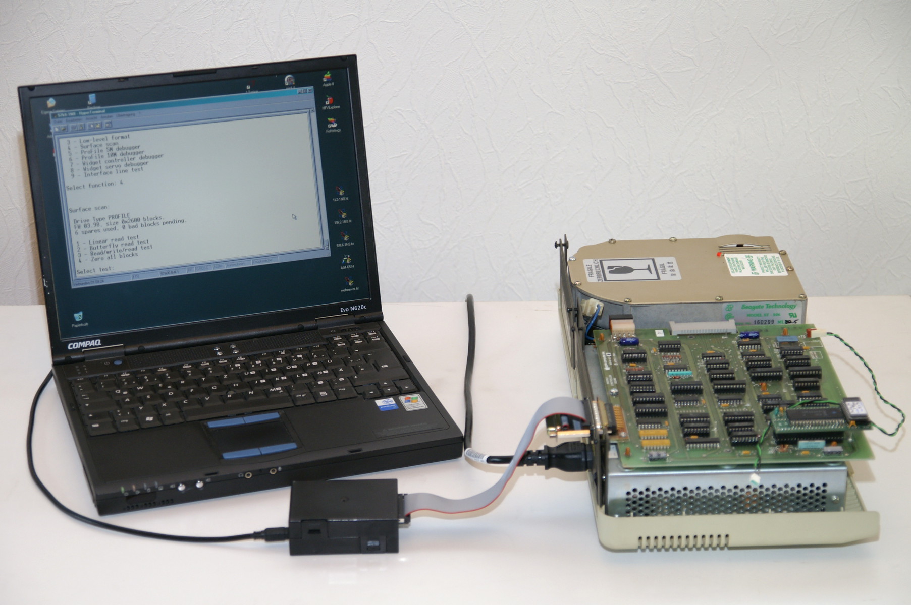 UsbWidEx is connected to the ProFile and to an USB port. ProFile is ready, its LED glows steady. On the Windows XP PC (with the FTDI driver installed), Hyperterminal is running at 57k6-8-1. Directly after connection, the status LED is red. Pressing any key at the terminal window wakes up UsbWidEx. The status LED goes off and the startup message appears:
UsbWidEx --- ProFile/Widget Debugger V1.02
 (c) Patrick Schaefer, 2012-14

  1 - Backup drive to file
  2 - Restore drive from file
  3 - Low-level format
  4 - Surface scan
  5 - ProFile 5M debugger
  6 - ProFile 10M debugger
  7 - Widget controller debugger
  8 - Widget servo debugger
  9 - Interface line test

Select function: 5

ProFile test mode selected.
> rffffff
 00FFFFFF6414 --> 00400000
"r" is the read command, that transfers a single block into the data buffer. In this case it is the status block -- number 0xFFFFFF. "00FFFFFF6414" is the binary representation of this command, as it is sent to the drive. "00400000" is what we get back from ProFile -- four bytes of status information. Besides that, 532 bytes of data are transferred into the data buffer, but not displayed yet.
If everything went fine, all four status bytes would be zero. Here, bit 6 in the second status byte is set, which means "spare table full". LisaOS would reject this drive and ask the user to contact the Authorized Apple Service. I guess today's iPhone experts would give up here. But let's go on...
> d
Command Buffer:
00400000 64140000 00000000 00000000
Data Buffer:
0000: 50524F46494C4520 2020202020000000 PROFILE ...
0010: 0398002600021420 2013001FE4001FE7 ..&... ...ä..ç
0020: 001FEA001FF80020 2200202300202400 ..ê..ø. ". #. $.
0030: 202A00202F002038 0020600020620020 *. /. 8. `. b.
0040: 6400206A00206C00 206D0020A00020A1 d. j. l. m. . ¡
0050: 0020E00020E10021 2000212300212A00 . à. á.! .!#.!*.
0060: 2160002220002267 0022680022EF0022 !`." ."g."h."ï."
0070: F000232000232600 25A0FFFFFF00035B ð.# .#&.% ÿÿÿ..[
0080: 000371000D31000D 5B000D71000DB100 ..q..1..[..q..±.
0090: 11B1001531001571 0015B10020630023 .±..1..q..±. c.#
00A0: 2700232800232A00 232F0024EA0025A7 '.#(.#*.#/.$ê.%§
00B0: 0025AA0025ACFFFF FF402A402F4001EA .%ª.%¬ @*@/@.ê
00C0: 40025B4071400431 405B407140B14003 @.[@q@.1@[@q@±@.
00D0: 31407140B14001B1 40B1FFFFFFFFFFFF 1@q@±@.±@±
00E0: FFFFDB6DDB6DDB6D DB6DDB6DDB6DDB6D ÛmÛmÛmÛmÛmÛmÛm
00F0: DB6DDB6DDB6DDB6D DB6DDB6DDB6DDB6D ÛmÛmÛmÛmÛmÛmÛmÛm
0100: DB6DDB6DDB6DDB6D DB6DDB6DDB6DDB6D ÛmÛmÛmÛmÛmÛmÛmÛm
0110: DB6DDB6DDB6DDB6D DB6DDB6DDB6DDB6D ÛmÛmÛmÛmÛmÛmÛmÛm
0120: DB6DDB6DDB6DDB6D DB6DDB6DDB6DDB6D ÛmÛmÛmÛmÛmÛmÛmÛm
0130: DB6DDB6DDB6DDB6D DB6DDB6DDB6DDB6D ÛmÛmÛmÛmÛmÛmÛmÛm
0140: DB6DDB6DDB6DDB6D DB6DDB6DDB6DDB6D ÛmÛmÛmÛmÛmÛmÛmÛm
0150: DB6DDB6DDB6DDB6D DB6DDB6DDB6DDB6D ÛmÛmÛmÛmÛmÛmÛmÛm
0160: DB6DDB6DDB6DDB6D DB6DDB6DDB6DDB6D ÛmÛmÛmÛmÛmÛmÛmÛm
0170: DB6DDB6DDB6DDB6D DB6DDB6DDB6DDB6D ÛmÛmÛmÛmÛmÛmÛmÛm
0180: DB6DDB6DDB6DDB6D DB6DDB6DDB6DDB6D ÛmÛmÛmÛmÛmÛmÛmÛm
0190: DB6DDB6DDB6DDB6D DB6DDB6DDB6DDB6D ÛmÛmÛmÛmÛmÛmÛmÛm
01A0: DB6DDB6DDB6DDB6D DB6DDB6DDB6DDB6D ÛmÛmÛmÛmÛmÛmÛmÛm
01B0: DB6DDB6DDB6DDB6D DB6D00004D0207B2 ÛmÛmÛmÛmÛm..M..²
01C0: FDF8000000000000 0000000015005052 ýø............PR
01D0: 4F46494C45202020 2020FFFFFFFFFFFF OFILE
01E0: FFFFFFFFFFFFFFFF FFFFFFFFFFFFFFFF
01F0: FFFFFFFFFFFFFFFF FFFFFFFFFFFFFFFF
0200: FFFFFFFFFFFFFFFF FFFFDB6DDB6DDB6D ÛmÛmÛm
0210: DB6DDB6D00000000 0000000000000000 ÛmÛm............
>
"d" displays both the 16 byte command and the 544 byte data buffer. The command buffer holds the command bytes before they are transmitted to the drive, and it stores the status bytes received back. Therefore we see our "00FFFFFF6414" overwritten by the "00400000" received.
In the data buffer is the contents of the status block 0xFFFFFF we have read before. The first line holds device name and type (000000), the second line firmware revision (3.98), device size (0x002600 blocks), block size (0x0214 bytes) and the number of spare blocks available (0x20). The byte at offset 0x0018 tells us the number of spares currently used (0x20, i.e. all of them) followed by the number of bad blocks pending (0x13). So we would need 19 more spare blocks than available on the disk! This unit needs to be formatted to put fresh adress marks on the platters.
Unfortunately the ROM size of the Z8 microcontroller inside ProFile is too small to hold both the user commands including bad block management and the diagnostic routines. Therefore the drive has to be opened and the Z8 has to be replaced with one with diagnostic firmware before formatting begins. After reconnection we can continue:
> !
 ProFile interface reset.

> g
 00FFFFFF6414 --> 00000000

Device Name:  PROFILE
Device Type:  000000
Firmware Rev: D3.11
Volume Size:  0x002600 blocks @ 0x0214 bytes
Spare Blocks: 20
Spares used:  00
Bad Blocks:   00
> f
*** close FMTEN jumper and press any key
 030000006414 --> 00000000
*** ok, remove FMTEN jumper
Instead of manually decoding the status block I have used the "get drive info" command. The diagnostic firmware does not contain any bad block management, therefore zero is reported for both the Spares Used and Bad Blocks Pending. We know better, so we can ignore this. "f" is the magic low level format command. Before formatting starts, a jumper has to be closed on the ProFile controller board. This allowes the Z8 to open the write gate at any time. Usually this is only possible after a the current sector's header matches the one of the sector that has to be written. For safety reasons this is checked by hardware, not by the microcontroller.
Now the write gate is opened continuously while the disk is spinning. This erases any old data and fills the whole track with zeroes. After that, 16 sector marks are written. A sector mark is approximately 20µs of DC, while a one or zero is represented by a flux transition. From these erased areas, the analog boards generates the sector pulses for the controller. In the second step, the sector headers are written. A header is a short piece of data that contains the address of the current sector (i.e. track, head and sector number). The controller board hardware uses this to identify each sector, it does not simply rely on counting sector marks. Finally, all sectors are filled with 0xD6B9. This is repeated for each of the four heads and for each of the 153 cylinders.
The last byte of the status tells us the number of errors occured. It is zero, so everything went fine. We can confirm this by looking a the data returned:
> d
Command Buffer:
00000000 64140000 00000000 00000000
Data Buffer:
0000: FFFFFFFF18915335 5737453274F4BA32 ÿÿÿÿ.S5W7E2tôº2
0010: 50E70910F5927BD1 F3B5221060704374 Pç..õ{Ñóµ".`pCt
0020: EAEE66346ABAA5B3 651EA1953AF6E2F0 êîf4jº¥³e.¡:öâð
0030: 2AB95802F191C3D7 E913F9B3BDB3713D *¹X.ñÃ×é.ù³½³q=
0040: A172BBB2B1B47F62 9EF0669A13B37376 ¡r»²±´.bðf.³sv
0050: BAD87117DD94E7D1 F2E3F4130363A2B0 ºØq.ÝçÑòãô..c¢°
0060: 9B1134BE25FAC5F3 A2F3DABB6118DF3F .4¾%úÅó¢óÚ»a.ß?
0070: 5FDD3376AD94EFD2 F3F31AC913AC2BF7 _Ý3vïÒóó.É.¬+÷
0080: ECF162927951BDE7 DFD7AAB171FFB515 ìñbyQ½çßת±qÿµ.
0090: 6AD0EDE568E24171 2B2975936035FA93 jÐíåhâAq+)u`5ú
00A0: 93B6FDB22BBEFFFE BEFA01B3633492BF ¶ý²+¾ÿþ¾ú.³c4¿
00B0: 72C4A9FE7BFB55F7 A0B2322666A632B7 rÄ©þ{ûU÷ ²2&f¦2·
00C0: 32D8E2F678B046D4 F4B7FB03329D53F6 2Øâöx°FÔô·û.2.Sö
00D0: B516772D18C2F493 60B80D39B7317077 µ.w-.Âô`¸.9·1pw
00E0: 53122F3FF0F299F8 FAD5E7B903000000 S./?ðòøúÕç¹....
00F0: 64145EB2B377944B F7F1F326FFFFFFFF d.^²³wK÷ñó&ÿÿÿÿ
0100: FFFFFFFFFFFFFFFF FFFFFFFFFFFFFFFF ÿÿÿÿÿÿÿÿÿÿÿÿÿÿÿÿ
0110: FFFFFFFFFFFFFFFF FFFFFFFFFFFFFFFF ÿÿÿÿÿÿÿÿÿÿÿÿÿÿÿÿ
0120: FFFFFFFFFFFFFFFF FFFFFFFFFFFFFFFF ÿÿÿÿÿÿÿÿÿÿÿÿÿÿÿÿ
0130: FFFFFFFFFFFFFFFF FFFFFFFFFFFFFFFF ÿÿÿÿÿÿÿÿÿÿÿÿÿÿÿÿ
0140: FFFFFFFFFFFFFFFF FFFFFFFFFFFFFFFF ÿÿÿÿÿÿÿÿÿÿÿÿÿÿÿÿ
0150: FFFFFFFFFFFFFFFF FFFFFFFFFFFFFFFF ÿÿÿÿÿÿÿÿÿÿÿÿÿÿÿÿ
0160: FFFFFFFFFFFFFFFF FFFFFFFFFFFFFFFF ÿÿÿÿÿÿÿÿÿÿÿÿÿÿÿÿ
0170: FFFFFFFFFFFFFFFF FFFFFFFFFFFFFFFF ÿÿÿÿÿÿÿÿÿÿÿÿÿÿÿÿ
0180: FFFFFFFFFFFFFFFF FFFFFFFFFFFFFFFF ÿÿÿÿÿÿÿÿÿÿÿÿÿÿÿÿ
0190: FFFFFFFFFFFFFFFF FFFFFFFFFFFFFFFF ÿÿÿÿÿÿÿÿÿÿÿÿÿÿÿÿ
01A0: FFFFFFFFFFFFFFFF FFFFFFFFFFFFFFFF ÿÿÿÿÿÿÿÿÿÿÿÿÿÿÿÿ
01B0: FFFFFFFFFFFFFFFF FFFFFFFFFFFFFFFF ÿÿÿÿÿÿÿÿÿÿÿÿÿÿÿÿ
01C0: FFFFFFFFFFFFFFFF FFFFFFFFFFFFFFFF ÿÿÿÿÿÿÿÿÿÿÿÿÿÿÿÿ
01D0: FFFFFFFFFFFFFFFF FFFFFFFFFFFFFFFF ÿÿÿÿÿÿÿÿÿÿÿÿÿÿÿÿ
01E0: FFFFFFFFFFFFFFFF FFFFFFFFFFFFFFFF ÿÿÿÿÿÿÿÿÿÿÿÿÿÿÿÿ
01F0: FFFFFFFFFFFFFFFF FFFFFFFFFFFFFFFF ÿÿÿÿÿÿÿÿÿÿÿÿÿÿÿÿ
0200: FFFFFFFFFFFFFFFF FFFFFFFFFFFFFFFF ÿÿÿÿÿÿÿÿÿÿÿÿÿÿÿÿ
0210: FFFFFFFF00000000 0000000000000000 ÿÿÿÿ............
0220: 000000000000640D 0000FF1CB0036600 ......d...ÿ.°.f.
> z
040000006414 --> 0000000E
The data buffer starts with 0xFFFFFFFF, which is the end of list marker. So the list is empty. In case of a fault, we would see four bytes indicating cylinder, head, sector and fault type. Fault type 0x80 means read timeout, 0xC0 CRC mismatch.
"z" starts a surface scan. The last byte of the status tells us that there are 14 bad sectors on the disk. So its surface is not perfect, but still okay. Note that a scan only reports faults, it does not fix them! Again, we can examine the results in detail:
> d
Command Buffer:
0000000E 64140000 00000000 00000000
Data Buffer:
0000: 0F030E0810020E08 16030E0820000508 ............ ...
0010: 34010B0834030108 35010B0835030108 4...4...5...5...
0020: 3603010854030108 5503010856010B08 6...T...U...V...
0030: 5603010857030108 FFFFFFFFBDB3713D V...W...ÿÿÿÿ½³q=
0040: A172BBB2B1B47F62 9EF0669A13B37376 ¡r»²±´.bðf.³sv
0050: BAD87117DD94E7D1 F2E3F4130363A2B0 ºØq.ÝçÑòãô..c¢°
0060: 9B1134BE25FAC5F3 A2F3DABB6118DF3F .4¾%úÅó¢óÚ»a.ß?
0070: 5FDD3376AD94EFD2 F3F31AC913AC2BF7 _Ý3vïÒóó.É.¬+÷
0080: ECF162927951BDE7 DFD7AAB171FFB515 ìñbyQ½çßת±qÿµ.
0090: 6AD0EDE568E24171 2B2975936035FA93 jÐíåhâAq+)u`5ú
00A0: 93B6FDB22BBEFFFE BEFA01B3633492BF ¶ý²+¾ÿþ¾ú.³c4¿
00B0: 72C4A9FE7BFB55F7 A0B2322666A632B7 rÄ©þ{ûU÷ ²2&f¦2·
00C0: 32D8E2F678B046D4 F4B7FB03329D53F6 2Øâöx°FÔô·û.2.Sö
00D0: B516772D18C2F493 60B80D390098030F µ.w-.Âô`¸.9...
00E0: 67FCF00000000000 0000000004000000 güð.............
00F0: D6B9D6B9D6B9D6B9 D6B9D6B9FFFFFFFF Ö¹Ö¹Ö¹Ö¹Ö¹Ö¹ÿÿÿÿ
0100: FFFFFFFFFFFFFFFF FFFFFFFFFFFFFFFF ÿÿÿÿÿÿÿÿÿÿÿÿÿÿÿÿ
0110: FFFFFFFFFFFFFFFF FFFFFFFFFFFFFFFF ÿÿÿÿÿÿÿÿÿÿÿÿÿÿÿÿ
0120: FFFFFFFFFFFFFFFF FFFFFFFFFFFFFFFF ÿÿÿÿÿÿÿÿÿÿÿÿÿÿÿÿ
0130: FFFFFFFFFFFFFFFF FFFFFFFFFFFFFFFF ÿÿÿÿÿÿÿÿÿÿÿÿÿÿÿÿ
0140: FFFFFFFFFFFFFFFF FFFFFFFFFFFFFFFF ÿÿÿÿÿÿÿÿÿÿÿÿÿÿÿÿ
0150: FFFFFFFFFFFFFFFF FFFFFFFFFFFFFFFF ÿÿÿÿÿÿÿÿÿÿÿÿÿÿÿÿ
0160: FFFFFFFFFFFFFFFF FFFFFFFFFFFFFFFF ÿÿÿÿÿÿÿÿÿÿÿÿÿÿÿÿ
0170: FFFFFFFFFFFFFFFF FFFFFFFFFFFFFFFF ÿÿÿÿÿÿÿÿÿÿÿÿÿÿÿÿ
0180: FFFFFFFFFFFFFFFF FFFFFFFFFFFFFFFF ÿÿÿÿÿÿÿÿÿÿÿÿÿÿÿÿ
0190: FFFFFFFFFFFFFFFF FFFFFFFFFFFFFFFF ÿÿÿÿÿÿÿÿÿÿÿÿÿÿÿÿ
01A0: FFFFFFFFFFFFFFFF FFFFFFFFFFFFFFFF ÿÿÿÿÿÿÿÿÿÿÿÿÿÿÿÿ
01B0: FFFFFFFFFFFFFFFF FFFFFFFFFFFFFFFF ÿÿÿÿÿÿÿÿÿÿÿÿÿÿÿÿ
01C0: FFFFFFFFFFFFFFFF FFFFFFFFFFFFFFFF ÿÿÿÿÿÿÿÿÿÿÿÿÿÿÿÿ
01D0: FFFFFFFFFFFFFFFF FFFFFFFFFFFFFFFF ÿÿÿÿÿÿÿÿÿÿÿÿÿÿÿÿ
01E0: FFFFFFFFFFFFFFFF FFFFFFFFFFFFFFFF ÿÿÿÿÿÿÿÿÿÿÿÿÿÿÿÿ
01F0: FFFFFFFFFFFFFFFF FFFFFFFFFFFFFFFF ÿÿÿÿÿÿÿÿÿÿÿÿÿÿÿÿ
0200: FFFFFFFFFFFFFFFF FFFFFFFFFFFFFFFF ÿÿÿÿÿÿÿÿÿÿÿÿÿÿÿÿ
0210: FFFFFFFF00000000 0000000000000000 ÿÿÿÿ............
0220: 000000000000640D 0000FF1CB0036600 ......d...ÿ.°.f.
> i
050000006414 --> 00000000
In the data buffer, we see 14 entries followed by the end-of-list flag. The structure is the same as for the format command: each entry consists of cylinder, head, sector and fault type. So there was a read timeout (0x80) on cylinder 16, head 3, sector 14. Later, these faulty blocks will be replaced by spares.
As a next step, the spares tracks are initialized. This is done with the "i" command. ProFile has four spares tracks, all of them are located on cylinder 77. The tracks accessed by head 2 and 3 hold 32 copies of the spare table (some kind of redundancy paranoia?), the tracks accessed by head 0 and 1 provide the 32 spare blocks which are used to replace bad data blocks. As before, the number of faults is reported in the last status byte. Here it is zero, but a small number on the spares tracks would not hurt -- there is enough redundancy!
With the regular R/W firmware installed, it is not possible to access the spares tracks. Remember that the diagnostic firmware addresses physical sectors (cylinder/head/sector), while the R/W firmware only knows logical blocks (LBA). There are no LBA assigned to the spares tracks, therefore they do not exist for LisaOS or Apple /// SOS. So let's take the rare opportunity to have a look at cylinder 77, head 2, sector 0!
> r4d0200
004D02006414 --> 00000000
> d
Command Buffer:
00000000 64140000 00000000 00000000
Data Buffer:
0000: 50524F46494C4520 2020202020000000 PROFILE ...
0010: D011002600021420 0000FFFFFFFFFFFF Ð..&... ..ÿÿÿÿÿÿ
0020: FFFFFFFFFFFFFFFF FFFFFFFFFFFFFFFF ÿÿÿÿÿÿÿÿÿÿÿÿÿÿÿÿ
0030: FFFFFFFFFFFFFFFF FFFFFFFFFFFFFFFF ÿÿÿÿÿÿÿÿÿÿÿÿÿÿÿÿ
0040: FFFFFFFFFFFFFFFF FFFFFFFFFFFFFFFF ÿÿÿÿÿÿÿÿÿÿÿÿÿÿÿÿ
0050: FFFFFFFFFFFFFFFF FFFFFFFFFFFFFFFF ÿÿÿÿÿÿÿÿÿÿÿÿÿÿÿÿ
0060: FFFFFFFFFFFF128E FFFFFFFFFFFFFFFF ÿÿÿÿÿÿ.ÿÿÿÿÿÿÿÿ
0070: FFFFFFFFFFFFFFFF FFFFFFFFFFFFFFFF ÿÿÿÿÿÿÿÿÿÿÿÿÿÿÿÿ
0080: FFFFFFFFFFFFFFFF FFFFFFFFFFFFFFFF ÿÿÿÿÿÿÿÿÿÿÿÿÿÿÿÿ
0090: FFFFFFFFFFFFFFFF FFFFFFFFFFFFFFFF ÿÿÿÿÿÿÿÿÿÿÿÿÿÿÿÿ
00A0: FFFFFFFFFFFFFFFF FFFFFFFFFFFFFFFF ÿÿÿÿÿÿÿÿÿÿÿÿÿÿÿÿ
00B0: FFFFFFFFFFFFFFFF FFFFFFFFFFFFFFFF ÿÿÿÿÿÿÿÿÿÿÿÿÿÿÿÿ
00C0: FFFFFFFFFFFFFFFF FFFFFFFFFFFFFFFF ÿÿÿÿÿÿÿÿÿÿÿÿÿÿÿÿ
00D0: FFFFFFFFFFFFFFFF FFFFFFFFFFFFFFFF ÿÿÿÿÿÿÿÿÿÿÿÿÿÿÿÿ
00E0: FFFFD6B9D6B9D6B9 6A7E0000D6B9D6B9 ÿÿÖ¹Ö¹Ö¹j~..Ö¹Ö¹
00F0: D6B9D6B9D6B9D6B9 D6B9D6B947C30000 Ö¹Ö¹Ö¹Ö¹Ö¹Ö¹GÃ..
0100: D6B9D6B9D6B9D6B9 D6B9D6B9D6B9D6B9 Ö¹Ö¹Ö¹Ö¹Ö¹Ö¹Ö¹Ö¹
0110: 47C30000D6B9D6B9 D6B9D6B9D6B9D6B9 GÃ..Ö¹Ö¹Ö¹Ö¹Ö¹Ö¹
0120: D6B9D6B947C30000 D6B9D6B9D6B9D6B9 Ö¹Ö¹GÃ..Ö¹Ö¹Ö¹Ö¹
0130: D6B9D6B9D6B9D6B9 47C30000D6B9D6B9 Ö¹Ö¹Ö¹Ö¹GÃ..Ö¹Ö¹
0140: D6B9D6B9D6B9D6B9 D6B9D6B947C30000 Ö¹Ö¹Ö¹Ö¹Ö¹Ö¹GÃ..
0150: D6B9D6B9D6B9D6B9 D6B9D6B9D6B9D6B9 Ö¹Ö¹Ö¹Ö¹Ö¹Ö¹Ö¹Ö¹
0160: 47C30000D6B9D6B9 D6B9D6B9D6B9D6B9 GÃ..Ö¹Ö¹Ö¹Ö¹Ö¹Ö¹
0170: D6B9D6B947C30000 D6B9D6B9D6B9D6B9 Ö¹Ö¹GÃ..Ö¹Ö¹Ö¹Ö¹
0180: D6B9D6B9D6B9D6B9 47C30000D6B9D6B9 Ö¹Ö¹Ö¹Ö¹GÃ..Ö¹Ö¹
0190: D6B9D6B9D6B9D6B9 D6B9D6B947C30000 Ö¹Ö¹Ö¹Ö¹Ö¹Ö¹GÃ..
01A0: D6B9D6B9D6B9D6B9 D6B9D6B9D6B9D6B9 Ö¹Ö¹Ö¹Ö¹Ö¹Ö¹Ö¹Ö¹
01B0: 47C30000D6B9D6B9 D6B9D6B9D6B9D6B9 GÃ..Ö¹Ö¹Ö¹Ö¹Ö¹Ö¹
01C0: D6B9D6B947C30000 D6B9D6B9D6B9D6B9 Ö¹Ö¹GÃ..Ö¹Ö¹Ö¹Ö¹
01D0: D6B9D6B9D6B9D6B9 47C30000D6B9D6B9 Ö¹Ö¹Ö¹Ö¹GÃ..Ö¹Ö¹
01E0: D6B9D6B9D6B9D6B9 D6B9D6B947C30000 Ö¹Ö¹Ö¹Ö¹Ö¹Ö¹GÃ..
01F0: D6B9D6B9D6B9D6B9 D6B9D6B9D6B9D6B9 Ö¹Ö¹Ö¹Ö¹Ö¹Ö¹Ö¹Ö¹
0200: 47C30000D6B9D6B9 D6B9D6B9D6B9D6B9 GÃ..Ö¹Ö¹Ö¹Ö¹Ö¹Ö¹
0210: D6B9D6B900000000 0000000000000000 Ö¹Ö¹............
0220: 000000000000640D 00303230300D0000 ......d..0200...
This is an empty spare table. Zero spares used, zero bad blocks pending. This internal format is slightly different from what we get when reading block 0xFFFFFF. First, the firmware version is D0.11, which is the version of the formatter tool used. ProFile's R/W software replaces this with its own version number at runtime, but does not change the value permanently. Second, there is no list of block numbers for the spared and bad blocks. Instead of this, there is a spare map that consists of 0x26 two-byte pointers. Each pointer represents 256 blocks (its number is the MSB of the block number) and points to a sublist which holds the LSBs of the spared or bad block's LBAs. The value 0x128E at offset 0x0066 indicates the start address of the sublist area in RAM.
Now the ProFile has to be powered down and the diagnostic Z8 is replaced with the regular one. After reconnection, the classic startup procedure takes place, including the surface scan accompanied by the flickering Ready light. When the Ready LED glows permanent, it is time to check the drive's condition:
> g
 00FFFFFF6414 --> 00000000

Device Name:  PROFILE
Device Type:  000000
Firmware Rev: 03.98
Volume Size:  0x002600 blocks @ 0x0214 bytes
Spare Blocks: 20
Spares used:  02
Bad Blocks:   0C

*** Spared Blocks:
   0011B1, 00155B,

*** Bad Blocks pending:
   0003FE, 00042E, 0005BE, 000805
   000D31, 000D5B, 000D71, 000DB1
   0014F1, 001531, 001571, 0015B1

>
Remember the "z" scan indicated 14 bad blocks. Two of them have been spared by the startup scan, the others have been entered into the bad block list. Up to now the R/W software did not decide whether these are really bad or not. Now it is a good time to run a surface test -- either on an Apple /// (using Apple's ProFile FST disk) or with the UsbWidEx Surface scan.
Four hours later, ProFile looks like this:
ProFile test mode selected.
> g
 00FFFFFF6414 --> 00008000

Device Name:  PROFILE
Device Type:  000000
Firmware Rev: 03.98
Volume Size:  0x002600 blocks @ 0x0214 bytes
Spare Blocks: 20
Spares used:  0F
Bad Blocks:   01

*** Spared Blocks:
   0003FE, 00042E, 0005BE, 000D1B
   000D31, 000D5B, 000D71, 000DB1
   0011B1, 0014B1, 0014F1, 001531
   00155B, 001571, 0015B1,

*** Bad Blocks pending:
   000805,
Now all bad blocks have been replaced by spares, except for 0x000805. This may be a weak one, so let's scrub on it for a while:
> r0805
 000008056414 --> 00000000
> y
 010008056424 --> 00000000
 010008056424 --> 00000000
 010008056424 --> 00000000
 010008056424 --> 00000000
 010008056424 --> 00000000
 010008056424 --> 00000000
 010008056424 --> 00000000
    (...)
 010008056424 --> 00000000
 010008056424 --> 00000000
 010008056424 --> 00000000
 010008056424 --> 00000000
 010008056424 --> 00000000
 010008056424 --> 00000000
 010008056424 --> 00000000
The "r"ead command acts as a seek -- setting up the controller for the desired block. "y" means loop on write, i.e. the sector is continuously overwritten until a key is pressed.
> g
 00FFFFFF6414 --> 00000000

Device Name:  PROFILE
Device Type:  000000
Firmware Rev: 03.98
Volume Size:  0x002600 blocks @ 0x0214 bytes
Spare Blocks: 20
Spares used:  0F
Bad Blocks:   00

*** Spared Blocks:
   0003FE, 00042E, 0005BE, 000D1B
   000D31, 000D5B, 000D71, 000DB1
   0011B1, 0014B1, 0014F1, 001531
   00155B, 001571, 0015B1,
> q
Now the bad block is gone. It may come back later, but then ProFile's R/W firmware will take care of it. A flaw in the magnetic surface is only noticeable if it affects a magnetic flux transition. Therefore it depends on the actual data written whether a block is useable or not.
This was the manual way to format a ProFile -- step by step. UsbWidEx' Low-level format function does the same, but requires less interaction. So does Apple's ProFile 5MB Format/Certify tool running on an Apple ///.
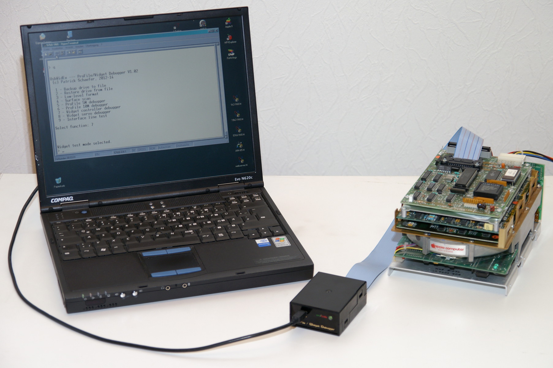 UsbWidEx is connected to the Widget and to an USB port. Widget has finished its power-on tests, the ready light is glowing steadily. On the Windows XP PC (with the FTDI driver installed), Hyperterminal is running at 57k6-8-1. Directly after connection, the status LED is red. Pressing any key at the terminal window wakes up UsbWidEx. The status LED goes off and the startup message appears:
UsbWidEx --- ProFile/Widget Debugger V1.02
 (c) Patrick Schaefer, 2012-14

  1 - Backup drive to file
  2 - Restore drive from file
  3 - Low-level format
  4 - Surface scan
  5 - ProFile 5M debugger
  6 - ProFile 10M debugger
  7 - Widget controller debugger
  8 - Widget servo debugger
  9 - Interface line test

Select function: 3

Low level format:

 Drive Type Widget-10
 FW 1A.45, size 0x4C00 blocks,
 74 spares used, 14 bad blocks pending.


WARNING: this will erase all data on your drive.
         Continue (y/n)? y
Sector offset (0..F, default 0):
Interleave set (0..5, default 1):

Checking selftest result...
Recalibrating...
Checking R/W circuit...
Recalibrating...
Formatting..................................................................
............................................................................
............................................................................
............................................................................
............................................................................
............................................................................
............................................................................
.........................
Restarting drive...
Initializung Spare Table...
Restarting drive...
Scanning surface...

Formatting done. Run surface test.
After starting the Low-level format function you will be asked for confirmation. Press <Y> to accept that this will erase any data on your drive, or any other key to abort and try a backup first. Now you can specify the offset between the index mark and the first sector and chose an interleave set. To accept the default values, just press <CR>. This will start the formatting process.
Widget's servo system uses two steps to position the R/W heads on the data tracks. In the first step, the heads are moved while lines on a glass scale attached to the drive frame are counted. This works similar to the quadrature encoders used in motor control systems. In the second step, fine positioning is done by searching the maximum amplitude on the read channel. This is called "automatic track following (ATF)". The difference between the coarse position indicated by the glass scale and the fine position determined from the amplitude maximum is called "track offset" or "ATF offset". Possible values are between -31 and +31.
To format a track, the heads are moved onto it using the coarse positioning system. After that, automatic track following is started and the ATF offset value is requested from the servo board. As long as this value is in the valid range, the new track will be written exactly onto the old one. In case of saturation (-31 or +31) the servo cannot access the perfect position, so the new track will be written slightly next to the old one. For ATF offset values bigger than 16 a warning is generated. Then the track is erased (filled with zeros), sector marks and headers are written and the data field is initialized. This is repeated for the second head, and then for the next cylinder.
Formatting a track requires three diagnostic commands, and there are 2 heads and 547 cylinders to go. Thanks to the invention of the for() loop we do not have to do this manually. But of course it is possible -- e.g. if only a couple of tracks need to be formatted and the rest should remain unchanged. After formatting is finished, the spares tracks are initialized. A 10MB Widget uses every 256th physical block as a spare, so a total of 76 spares are available. Two of these are used for the spare tables themselves, the rest is available to replace bad data blocks.
Finally, a surface scan is done which -- in contrast to the ProFile algorithm -- replaces any bad blocks found with spares. Nevertheless, it is a good idea to run the Surface scan a couple of times.
UsbWidEx --- ProFile/Widget Debugger V1.02
 (c) Patrick Schaefer, 2012-14

  1 - Backup drive to file
  2 - Restore drive from file
  3 - Low-level format
  4 - Surface scan
  5 - ProFile 5M debugger
  6 - ProFile 10M debugger
  7 - Widget controller debugger
  8 - Widget servo debugger
  9 - Interface line test

Select function: 4

Test drive surface:

 Drive Type Widget-10
 FW 1A.45, size 0x4C00 blocks,
 2 spares used, 0 bad blocks pending.

 1 - Linear read test
 2 - Butterfly read test
 3 - Read/write/read test
 4 - Zero all blocks

Select test: 3

WARNING: this will erase all data on your drive.
         Continue (y/n)? y


Pass 1: read each block.....................................................
.......................
Pass 2: write each block....................................................
........................
Pass 3: read each block.....................................................
.......................
No errors.
In the first pass, all blocks are read once. If Widget detects any weak or unreadable ones, these will be marked bad. Pass 2 overwrites each block with a test pattern followed by a CRC value. Blocks marked bad that can be overwritten without any issues are released, bad blocks that cause write errors are replaced with spares. In the last pass, all blocks are read back and the CRC is checked. This ensures that the data transfer between Widget and UsbWidEx is working properly. As usual, there is a confirmation request before data on the drive will be overwritten.
UsbWidEx is connected to the Widget and to an USB port. Widget has finished its power-on tests, the ready light is glowing steadily. On the Windows XP PC (with the FTDI driver installed), Hyperterminal is running at 57k6-8-1. Directly after connection, the status LED is red. Pressing any key at the terminal window wakes up UsbWidEx. The status LED goes off and the startup message appears:
UsbWidEx --- ProFile/Widget Debugger V1.02
 (c) Patrick Schaefer, 2012-14

  1 - Backup drive to file
  2 - Restore drive from file
  3 - Low-level format
  4 - Surface scan
  5 - ProFile 5M debugger
  6 - ProFile 10M debugger
  7 - Widget controller debugger
  8 - Widget servo debugger
  9 - Interface line test

Select function: 7

Widget test mode selected.
> g

Device Name:  Widget-10
Device Type:  000100
Firmware Rev: 1A.45
Volume Size:  0x004C00 blocks @ 0x0214 bytes
Spare Blocks: 76
Spares used:  2
Bad Blocks:   0
Run number:   00000004
Sector offset 0, interleave set 1

*** Spare Table:
  Spare block 25 is a spare table at LBA 001955
  Spare block 24 is spare for block 001988
  Spare block 26 is spare for block 001A32
  Spare block 50 is a spare table at LBA 0032AA
This is the Widget-10 drive that has been formatted in the last session. Use the get drive info command "g" to read the status block 0xFFFFFF and decode its contents. Two spare blocks have been used to replace bad sectors, two others hold the spare tables. So there are 72 left (not 74!). The Run number tells us how often the spare table has been updated. This occurs once during the power-on self test, and then each time a data block is spared. Though LBA values are given for both spare tables, these don't have any meaning and cannot be accessed by the host.
To read the spare table, use the read spare table command "m".
> m
120DE0 --> 00000000
> d
Command Buffer:
00000000 641E3C1E 14000000 00000000
Data Buffer:
0000: F0783C1E00000004 0001808080808080 ðx<.......
0010: 1980808080803280 8080808080808080 .2
0020: 8080808080808080 8080808080808080
0030: 8080808080808080 8080808080808080
0040: 8080808080808080 8080808080808080
0050: 8080808080808080 8080808080808080
0060: 8080808080808080 8080808080808080
0070: 8080808080808080 8080808080808080
0080: 8080808080808080 80800200000000E0 .....à
0090: 0000200000000000 0000000000000000 .. .............
00A0: 0000000000000000 0000000000000000 ................
00B0: 0000000000000000 0000000000000000 ................
00C0: 0000000000000000 0000000000000000 ................
00D0: 0000000000000000 0000000000000000 ................
00E0: 0000000000000000 0000000000000000 ................
00F0: 0000000000007201 881A78015518F202 ......r..x.U.ò.
0100: 3200000000000000 0000000000000000 2...............
0110: 0000000000000000 0000000000000000 ................
0120: 0000000000000000 0000000000000000 ................
0130: 0000000000000000 0000000000000000 ................
0140: 0000000000000000 0000000000000000 ................
0150: 0000000000000000 000000000000F802 ..............ø.
0160: AA00000000000000 0000000000000000 ª...............
0170: 0000000000000000 0000000000000000 ................
0180: 0000000000000000 0000000000000000 ................
0190: 0000000000000000 0000000000000000 ................
01A0: 0000000000000000 0000000000000000 ................
01B0: 0000000000000000 0000000000000000 ................
01C0: 000000000000000C 05110A030F08010D ................
01D0: 06120B041009020E 074784F0783C1E00 .........Gðx<..
01E0: 0000000021000000 0000000000000000 ....!...........
01F0: 0000000000000000 0000000000000000 ................
0200: F0783C1E00000000 0000000000000000 ðx<.............
0210: 0000000000000000 0000000000000000 ................
0220: 0000000000000000 0000000000000000 ................
"F0783C1E" indicates the start of a spare table. "00000004" is the run number. The next two bytes contain the sector offset during formatting (0x00) and the interleave set used (0x01). The spare table itself is a set of lists, starting at offset 0x000A. There is a pointer for each group of 1024 sectors that points into a heap area. This heap area contains the remaining part of the block number for each spare, and a pointer to the next one.
As an example, pointer #06, which belongs to LBA 0x001800..0x001BFF (6*1024), has the value 0x19. It points to the 25th (0x19) spare in the heap area (at offset 0x00FA). The entry "78 0155 18" gives us the lower part of the block LBA. 0x001800 + 0x0155 = 0x001955 -- this is the number of the spared block. "78" indicates the type of spare: 0x78 means a spare table and 0x72 a spared data block. The last byte is a pointer to the next spare in this chain, number 24 (0x18). Spare 24 has the value "72 0188 1A". This means data block 0x001800 + 0x0188 = 0x001988 has been replaced by spare block 0x18, and the chain continues with spare number 26 (0x1A). Spare 26 with its value "F2 0232 00" replaces data block 0x001800 + 0x0232 = 0x001A32. The chain ends here, because the pointer to the next spare has the value 0 (nil). Here is a textfile with some more examples. If you don't want to parse the list by yourself, just use the "g" command.
The spare table is followed by a map table which starts at offset 0x01C6. This map table, together with the physical interleave specified during formatting, defines the logical order of the data blocks on a track. Together with an 1:1 interleave the standard map table
000C05110A030F08 010D06120B041009020E07
results in an interleave of 1:8.
You can read any data block using the "r"ead command, and write it back with the "w"rite or "v"erify/write command. Reading LBA 0xFFFFFF gets us the drive status block:
> rffffff
00FFFFFF6414 --> 00000000
> d
Command Buffer:
00000000 64143C1E 15000000 00000000
Data Buffer:
0000: 5769646765742D31 3020202020000100 Widget-10 ...
0010: 1A45004C00021402 02021300004C0000 .E.L.........L..
0020: 0000000000018080 8080808080808080 ......
0030: 8080808080808080 8080808080808080
0040: 8080808080808080 8080808080808080
0050: 8080808080808080 8080808080808080
0060: 8080808080808080 8080808080808080
0070: 8080808080808080 8080808080808080
0080: 8080808080808080 8080000000000040 .....@
0090: 0000200000000000 0000000000000000 .. .............
00A0: 0000000000000000 0000000000000000 ................
00B0: 0000000000000000 0000000000000000 ................
00C0: 0000000000000000 0000000000000000 ................
00D0: 0000000000000000 0000000000000000 ................
00E0: 0000000000000000 0000000000000000 ................
00F0: 0000000000000000 0000F80155000000 ..........ø.U...
0100: 0000000000000000 0000000000000000 ................
0110: 0000000000000000 0000000000000000 ................
0120: 0000000000000000 0000000000000000 ................
0130: 0000000000000000 0000000000000000 ................
0140: 0000000000000000 0000000000000000 ................
0150: 0000000000000000 000000000000F802 ..............ø.
0160: AA00000000000000 0000000000000000 ª...............
0170: 0000000000000000 0000000000000000 ................
0180: 0000000000000000 0000000000000000 ................
0190: 0000000000000000 0000000000000000 ................
01A0: 0000000000000000 0000000000000000 ................
01B0: 0000000000000000 0000000000000000 ................
01C0: 000000000000000C 05110A030F08010D ................
01D0: 06120B041009020E 074511F0783C1E00 .........E.ðx<..
01E0: 0000000025000000 0000000000000000 ....%...........
01F0: 0000000000000000 0000000000000000 ................
0200: F0783C1E00000000 0000000000000000 ðx<.............
0210: 0000000000000000 0000000000000000 ................
Probably the most important command is "s", to read Widget's status registers. This allows us to query the internal fault memories of Widget's controller and servo boards. Without this information, repairs are almost impossible.
Widget has three sets of status registers. "s0" returns the controller status, "s1"
the servo status, and "s2" the abort status. Controller and Servo status consist of eight blocks with four bytes each. When reading the Servo status, the regular command completion status from the controller is sent as well, so only the last four bytes in each line are important. The Abort status is 16 bytes long, again preceeded by 4 bytes command completion status.
With no parameter given, 's' returns the Controller status:
> r0
 000000006414 --> 00000000
> s
 130100EB --> 00: 00000000
 130101EA --> 01: 00000000
 130102E9 --> 02: 00000000
 130103E8 --> 03: 00000000
 130104E7 --> 04: 80C20002
 130105E6 --> 05: 0000DBE0
 130106E5 --> 06: 20002000
 130107E4 --> 07: 02350100
The meaning of the controller and abort status bytes is explained in the "Widget Firmware Specification (Widget ERS)". This document is available at bitsavers.org. The "s0" command can also be issued as "s0,1", which gives a description of the status bits:
> r0
 000000006414 --> 00000000
> s0,1
 130100EB --> 00: 00000000
 Standard Status: ok
 130101EA --> 01: 00000000
 Last logical block: 000000
 130102E9 --> 02: 00000000
 Last seek to cylinder 0000, head 00, sector 00
 130103E8 --> 03: 00000000
 Current cylinder: 0000
 130104E7 --> 04: 80C20002
 Internal Status:
  Auto recovery on
  Heads on track
  Read a header after recal
  Seek complete
  Servo Auto-Offset is off
 130105E6 --> 05: 0000DBE0
 Controller selftest passed
 Z8 port 2:
  * Disk R/W direction set to Read
  * SIOrdy = 1
  * MSel1  = 0
  * MSel0  = 1
  * /PBusy = 1
  * /PCmd  = 0
  * ECC ok
  * State machine is stopped
 I/O control port 0x1F00:
  * CRC ok
  * Write valid
  * ServoRdy = 1
  * ServoErr = 0
  State machine state 0
 130106E5 --> 06: 20002000
 Last Read operation:
  At least one retry was successful, valid data in buffer
 Last Write operation:
  At least one retry was successful
 130107E4 --> 07: 02350100
  Last seek came from cylinder 0235, head 01, sector 00
>
>
> r4bff
 00004BFF6414 --> 00000000
> s0,1
 130100EB --> 00: 00000000
 Standard Status: ok
 130101EA --> 01: 00004BFF
 Last logical block: 004BFF
 130102E9 --> 02: 02010107
 Last seek to cylinder 0201, head 01, sector 07
 130103E8 --> 03: 02010201
 Current cylinder: 0201
 130104E7 --> 04: 80C20002
 Internal Status:
  Auto recovery on
  Heads on track
  Read a header after recal
  Seek complete
  Servo Auto-Offset is off
 130105E6 --> 05: 0000DBE0
 Controller selftest passed
 Z8 port 2:
  * Disk R/W direction set to Read
  * SIOrdy = 1
  * MSel1  = 0
  * MSel0  = 1
  * /PBusy = 1
  * /PCmd  = 0
  * ECC ok
  * State machine is stopped
 I/O control port 0x1F00:
  * CRC ok
  * Write valid
  * ServoRdy = 1
  * ServoErr = 0
  State machine state 0
 130106E5 --> 06: 20002000
 Last Read operation:
  At least one retry was successful, valid data in buffer
 Last Write operation:
  At least one retry was successful
 130107E4 --> 07: 00000100
  Last seek came from cylinder 0000, head 01, sector 00
Finally, let's park the drive heads:
> p
 1208E5 --> 00000000
>
>
In the previous examples, UsbWidEx was connected to the Widget controller board. This means we used the same data path as the Lisa. Now we go down one level and talk directly to the drive mechanism. Therefore UsbWidEx is attached to the 40 pin card-edge connector of the motherboard, which carries the raw data streams for reading and writing, the servo control signals, and provides the power supply.
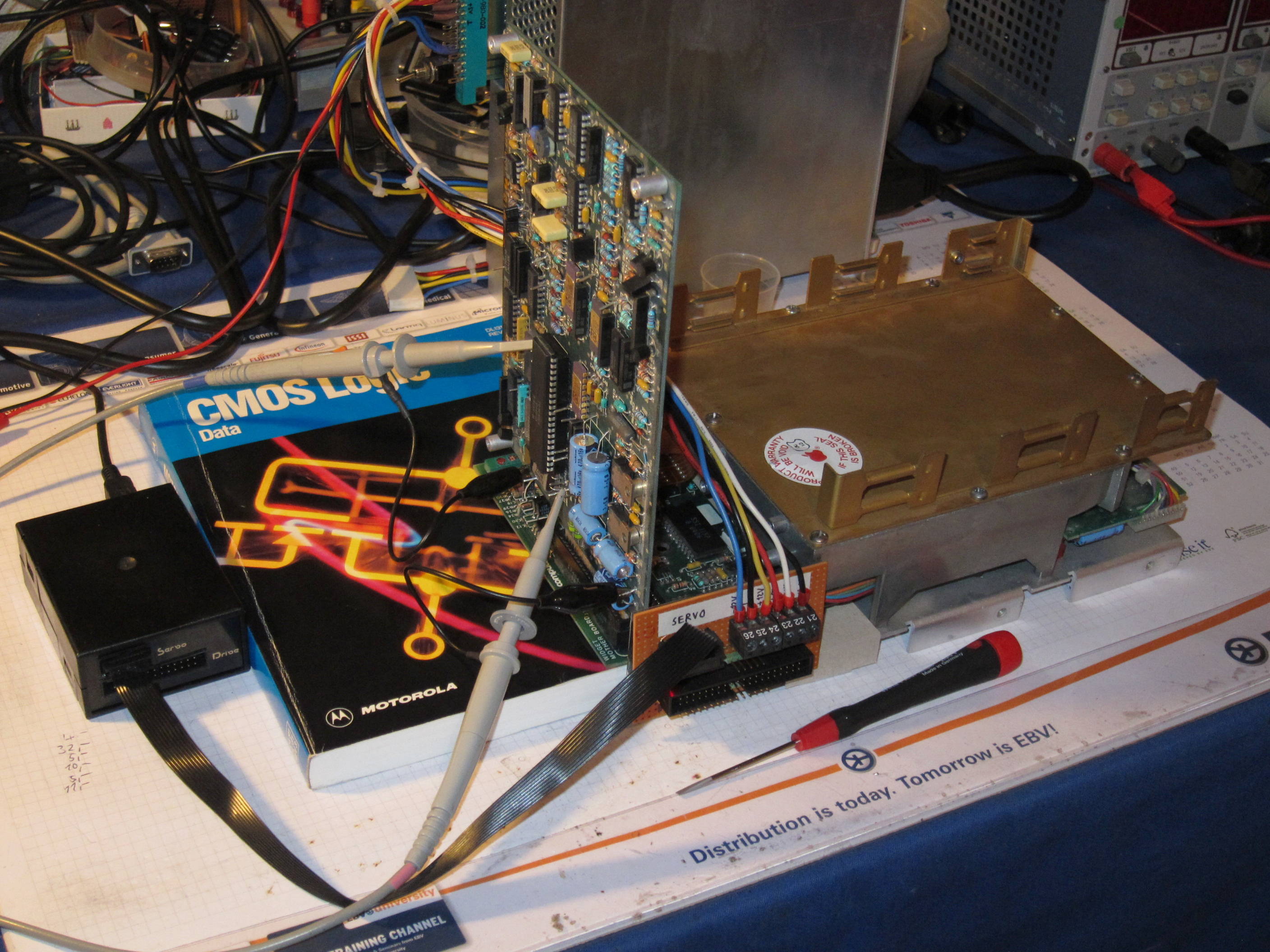
For servo adjustment, all PCBs have to be removed from the motherboard. The motherboard itself needs to be unscrewed and tilted by 90° so that the two groups of potentiometers are easily accessible. Use some insulating support to reduce stress on the foil cables to a minimum. Put the servo board back into the upper (now leftmost) slot.
For servo adjustment, the motherboard needs to be separated from the HDA mechanism. Place it onto an insulating surface of suitable thickness -- a Motorola data book is just fine.
 |
 |
Widget's servo system consists of two parts: a coarse position servo that moves the heads to the desired cylinder, guided by an optical quadrature encoder, and a fine position servo that centers the heads on the track by searching for the strongest data signal. In order to compensate for mechanical tolerances, the optical encoder must be set. In addition, the dynamic properties of the system (tacho gain and offset) are adapted to the mechanics. To make this possible, seven potentiometers and a socketed resistor
are provided on the mainboard.

1) Adjust the widget optics as follows:
UsbWidEx is connected to the 40 pin card-edge connector of the Widget motherboard and to an USB port. Power has been applied and the drive is spinning at nominal speed. On the Windows XP PC (with the FTDI driver installed), Hyperterminal is running at 57k6-8-1. Directly after connection, the status LED is red. Pressing any key at the terminal window wakes up UsbWidEx. The status LED goes off and the startup message appears:
UsbWidEx --- ProFile/Widget Debugger V1.02
 (c) Patrick Schaefer, 2012-14

  1 - Backup drive to file
  2 - Restore drive from file
  3 - Low-level format
  4 - Surface scan
  5 - ProFile 5M debugger
  6 - ProFile 10M debugger
  7 - Widget controller debugger
  8 - Widget servo debugger
  9 - Interface line test

Select function: 8

Servo test mode selected.
>
Measure the voltage at TP5 on the mainboard. It should be 3.6 V +/- 0.2 V, which means 20 mA LED current. Adjust with the LED current pot. If the setting range is not sufficient it may be necessary to adjust R34. On most boards this resistor is in a socket.
Note: 3.6 V is the specification value. Some of my (good) drives measure lower voltages. Leave it as it is if it works. More current means more stress to the LED.
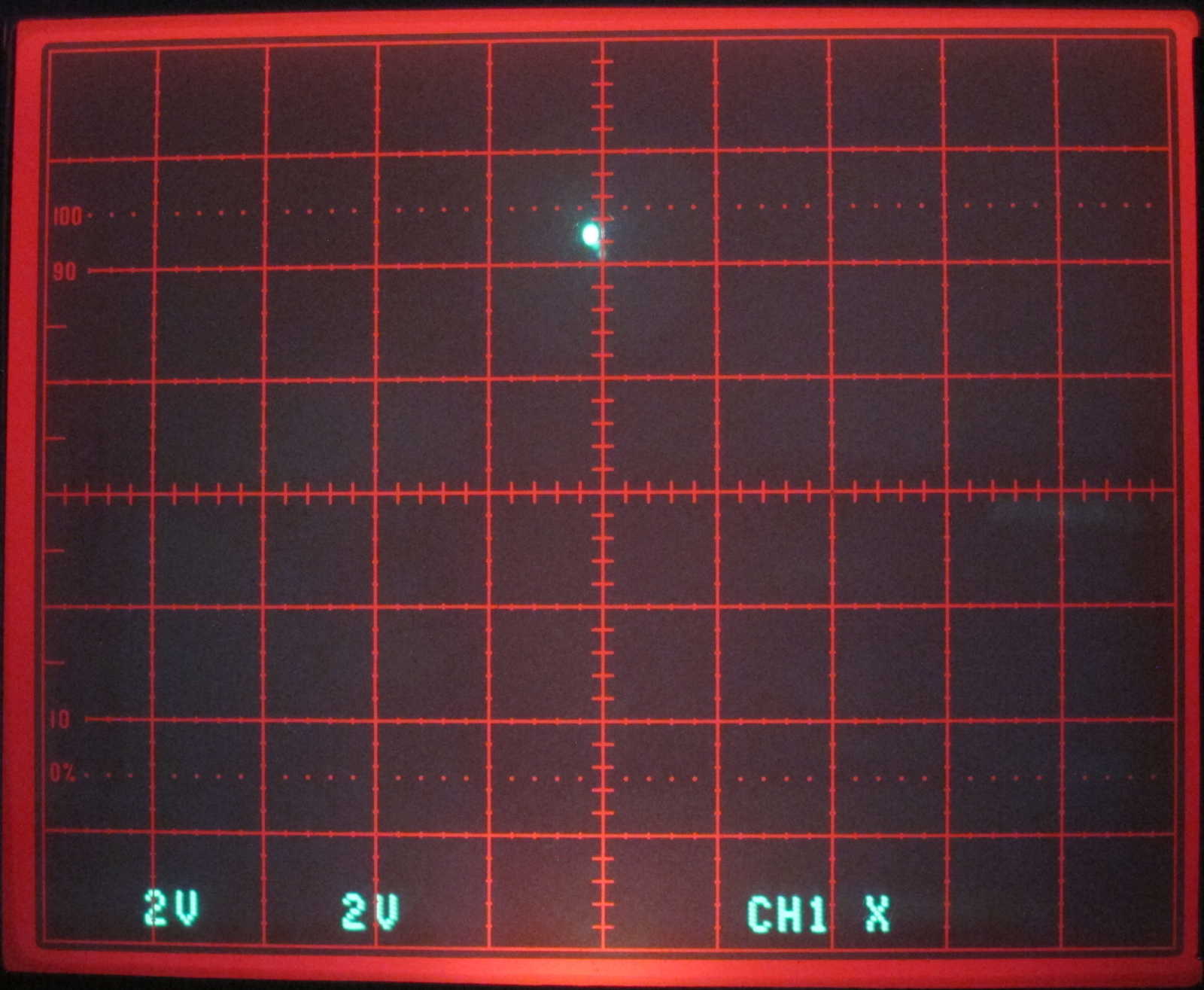
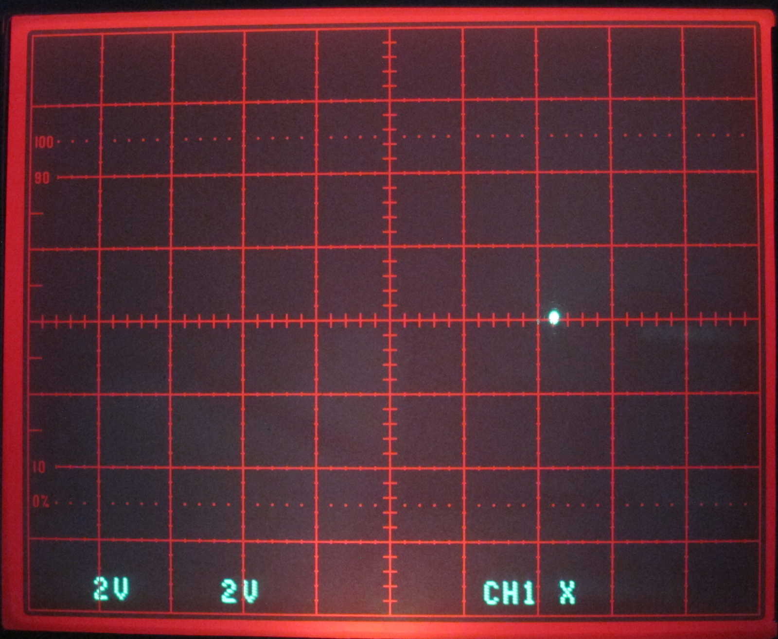
Now set your oscilloscope to X-Y mode, 2 V/div, and center the spot. Connect channel 1 to testpoint TP9 (POS_B) and channel 2 to TP8 (POS_A) on the servo board. Both testpoints are labelled and located between the Z8 microcontroller and the card edge connector, next to the crystal. At the terminal window, enter "!" to trigger a servo reset. This will release the head assembly brake and you will hear a loud click. "r" restores the heads to the recal position at track 72. This is the first track used for data storage. Now the spot should be in the upper center of the oscilloscope screen.
> !
Servo reset.
> r
 40000000BF --> ok
>
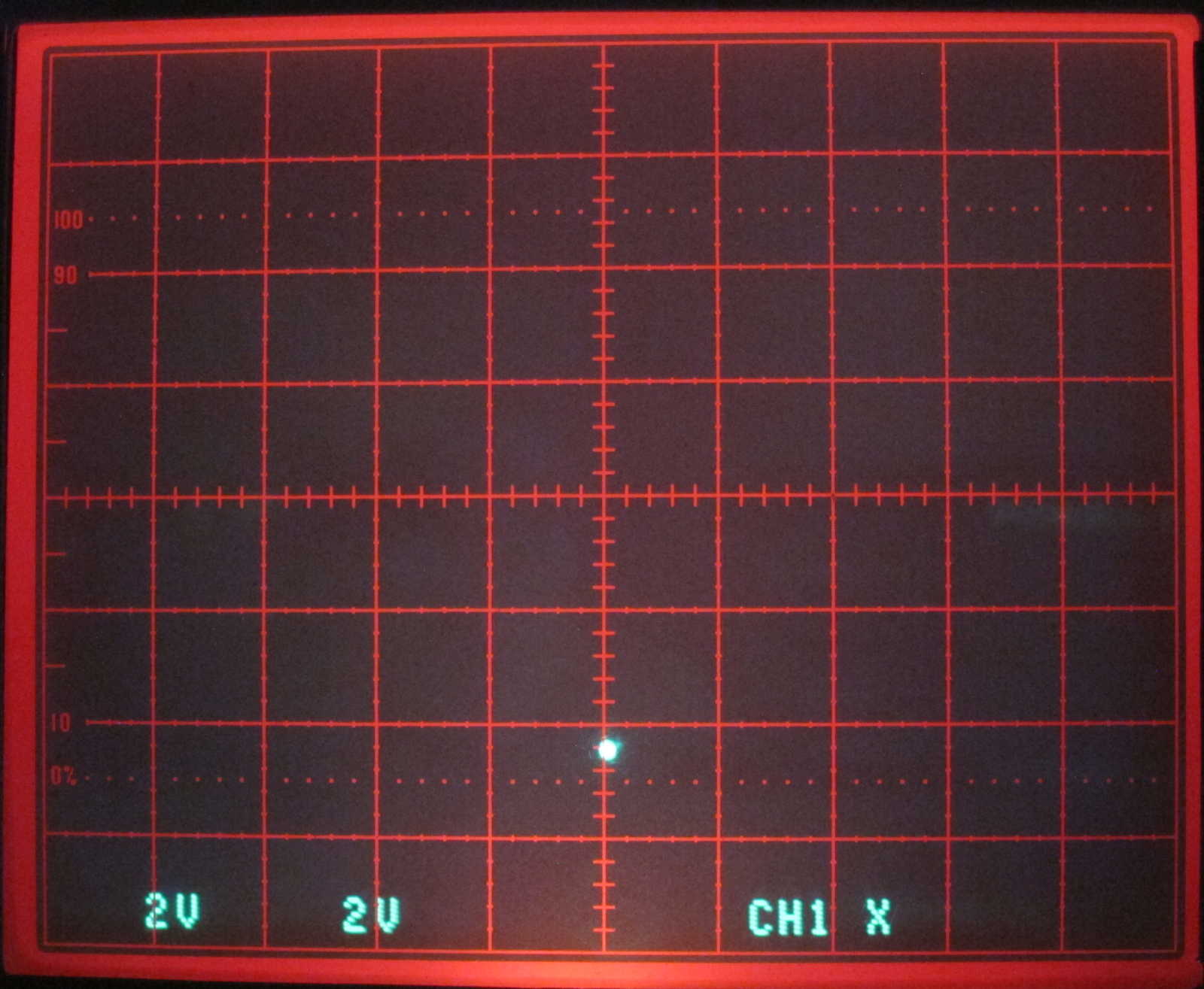
On the mainboard is a quad potentiometer which sets the gain for bottom, left, right, and top position. Adjust the "top" pot until the spot is 5 V above the zero position. Now enter "f" to seek forward to the next track. The spot moves to the right position. Adjust the "right" pot for 5 V and repeat this for the bottom and left postion. Turn another round and verify all four positions.
Note: If some servo action fails (return code "--> failed") SERVOERR has to be cleared by reading the status registers before the next command can be sent. Enter "s" to do this.
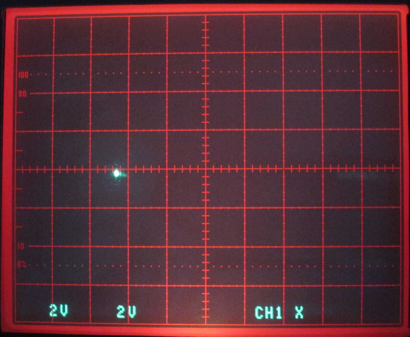
To check alignment, start an alternate seek with an amplitude of +/- 0x100 tracks. The required command is "a100". You will see a circle on the oscilloscope screen. Fine-tune the four pots for best symmetry. Pressing any key will stop the alternate seek. Enter "r" to move the heads back to the recalibrate position.
Note that all head motion is relative and there is no range check! Always make sure there is enough space before sending seek requests. From the recal position it is safe to seek forward 0x200 tracks.
Encoder output signal for four adjacent tracks. Use the "f" forward seek command to move the heads to the next cylinder. The Lissajous figure in the picture on the right is the result of an alternate seek ("a100").
 |
 |
 |
 |
 |
The LED current has an influence on the size of the circle. If it looks good but is just to big, reduce LED current and leave the other controls as they are.
2) The next step is to adjust the dynamic behavior of the servo.
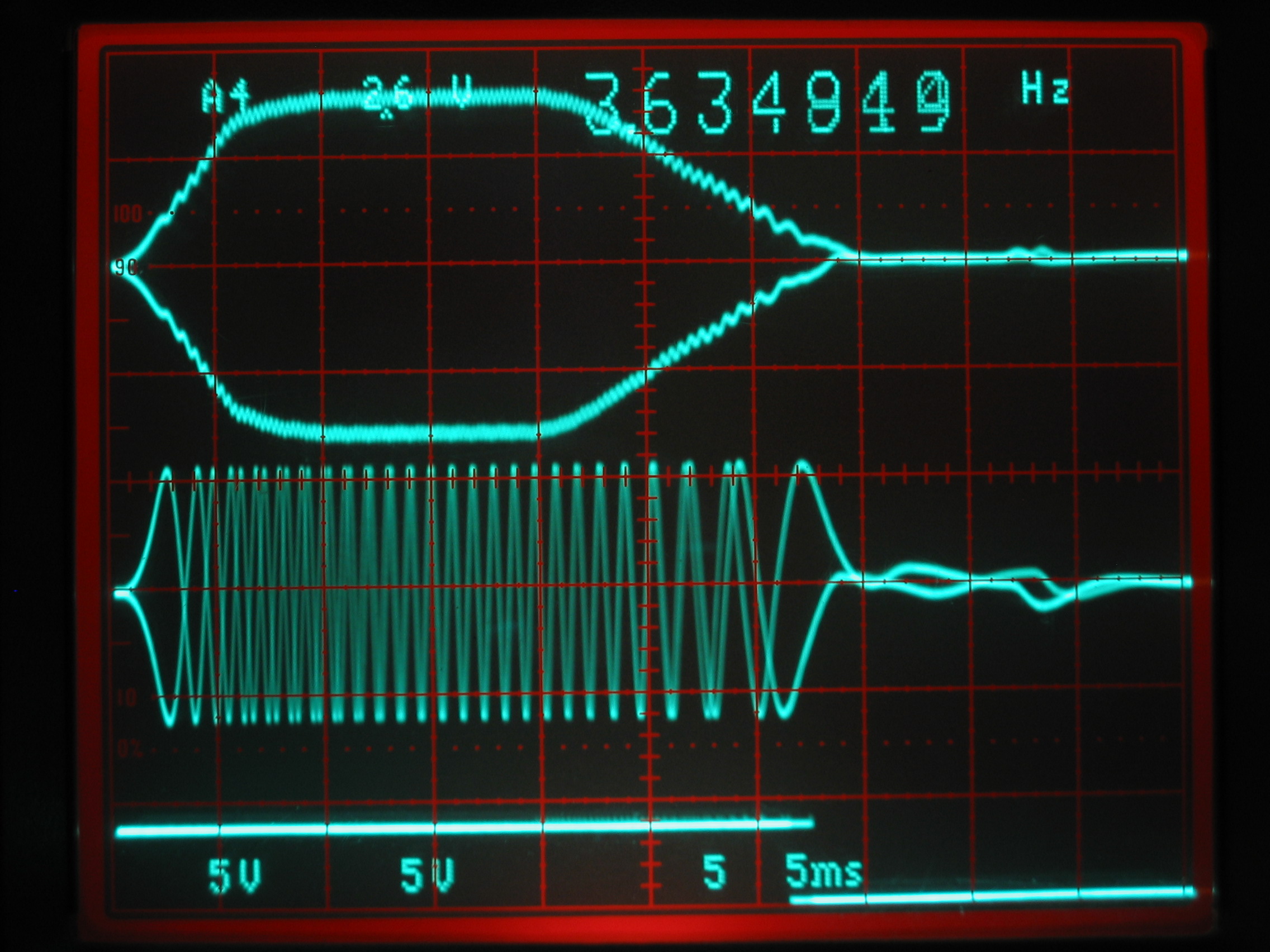
Set the oscilloscope to regular timebase mode with 5 ms per division. Leave channel 1 connected to TP9 (POS_B) and connect channel 2 to TP27 (ACCESS_MODE). TP27 is close to pin 21 of the Z8, the top one in the group of three. Trigger on the rising slope of ch 2. Now recalibrate ("r") and start an alternate seek with an amplitude of +/-90 (0x60) tracks ("a60"). Adjust the Tach Gain pot on the mainboard so that the waveform is 35 ms long.
Left image: current sense (TP19), position B (TP9) and Access Mode (TP27), right image: velocity (TACH, TP7), position B (TP9) and Access Mode (TP27). Both diagrams have been captured during an alternate seek with an amplitude of +/-96 tracks ("a60").
 |
 |
Press any key to stop seeking and enter "r" to recalibrate. Measure the voltage at TP7 (TACH) and adjust the Tach Offset pot for zero volts (+/- 0.05 V).
Start some alternate seeks with different amplitudes to exercise the servo. If the system aborts (response "--> failed") or overshoots and bangs into the endstop, reduce Tach Gain a little bit. Most Widgets have some irregular friction in their bearings which makes it difficult for the servo to maintain a constant velocity. Cleaning and lubricating the bearings would be the correct remedy, but unfortunately it is not possible to dismantle the head assembly without causing permanent damage to the drive mechanism. Rememember to read the servo status after each fault ("s" command) to clear the SERVOERR flag.
Finally, recalibrate and start a butterfly seek over 512 tracks. The required command is "b200". Recheck the Lissajous figure. For a good drive it has an almost constant amplitude. With mechanically misaligned optics the diameter will depend on the position of the heads. In that case set the amplitude so that the radius is between 4 and 5 V over the full range.
To park the heads before removing power, recalibrate ("r") and seek forward by 0x200 tracks ("f200").
UsbWidex is copyright (c) by Dr. Patrick Schäfer, 2014
Apple, Lisa, ProFile, Widget and the ProFile communications protocol are (c) by Apple Computer Inc.
----> Back to the UsbWidEx page
----> Back to my home page
This page is hosted at John, a server of the Computer Club der RWTH Aachen e.V.
