 |
 |
Vintage hardware has one great advantage: everything is bigger. Components were less specialized and integration density was much lower these days. This allows us to have schematics where you can understand a system in detail instead of looking at a block diagram. And it allows us to monitor signals in realtime instead of watching VHDL simulation traces. This article contains some logic diagrams captured with a logic analyzer to show the inner workings of an Apple Widget Hard Disk. Besides that, a couple of measurement results are given that may help you to troubleshoot your drive. Or just give you some better understanding what the engineers at Apple's Drive Division designed in 1983.
|
|
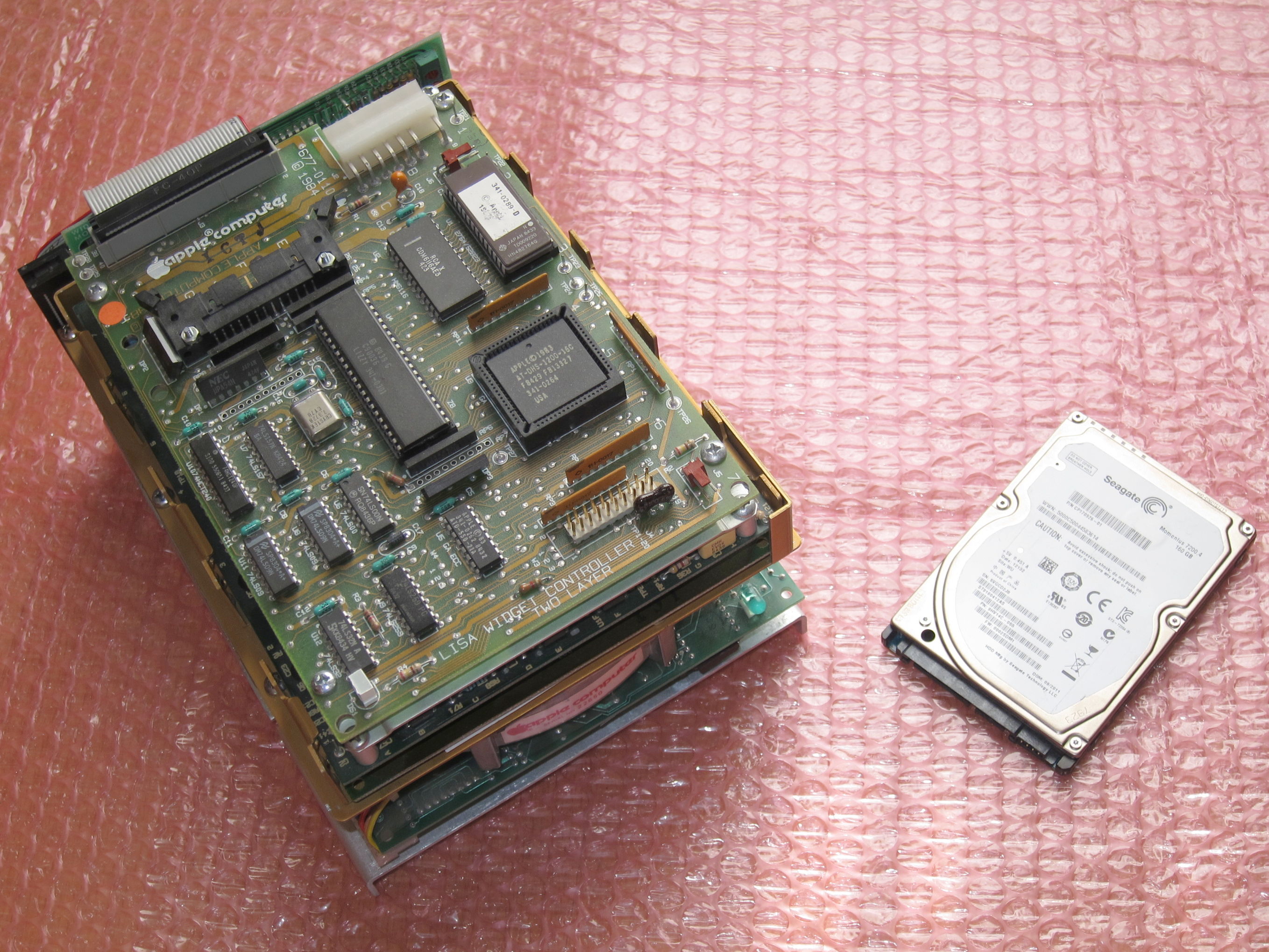
If you are interested in the firmware controlling the drive: commented sources for the as assembler are available at bitsavers.org. Here is the code for Widget Controller and Servo and here is the code for both ProFile and ProFile 10M. All drives use Zilog Z8 microcontrollers with internal mask ROM or external EPROM memory. During development, Piggyback devices have been used where the internal mask ROM is substituted by an EPROM sitting on the back of the controller. Some of these pre-series units even made it into series production!
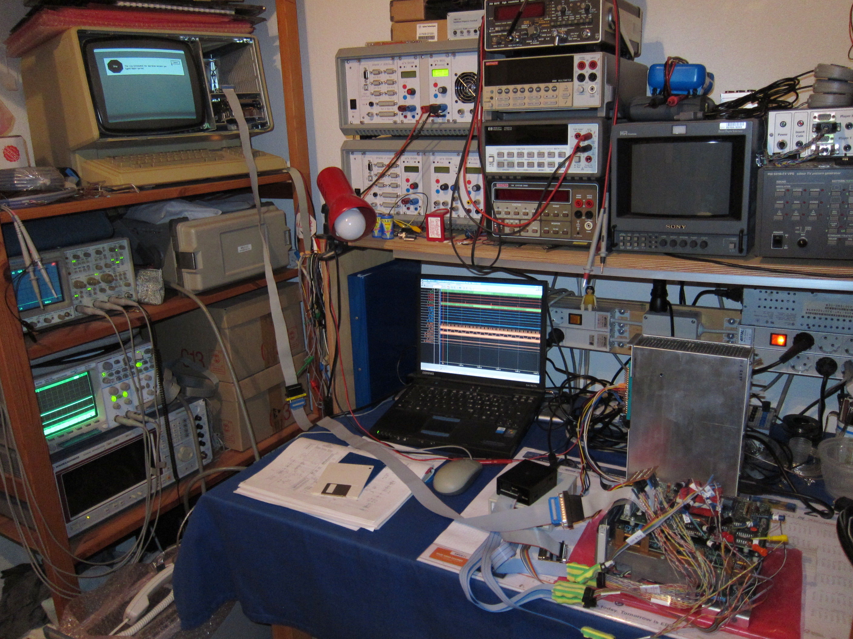
Timing diagrams have been captured with a miniLA USB Logic Analyzer. This is a DIY device able to capture up to 32 signals with up to 100 MHz sample rate. To view the raw data you will need the "miniLA Windows EXE" software available here.
 |
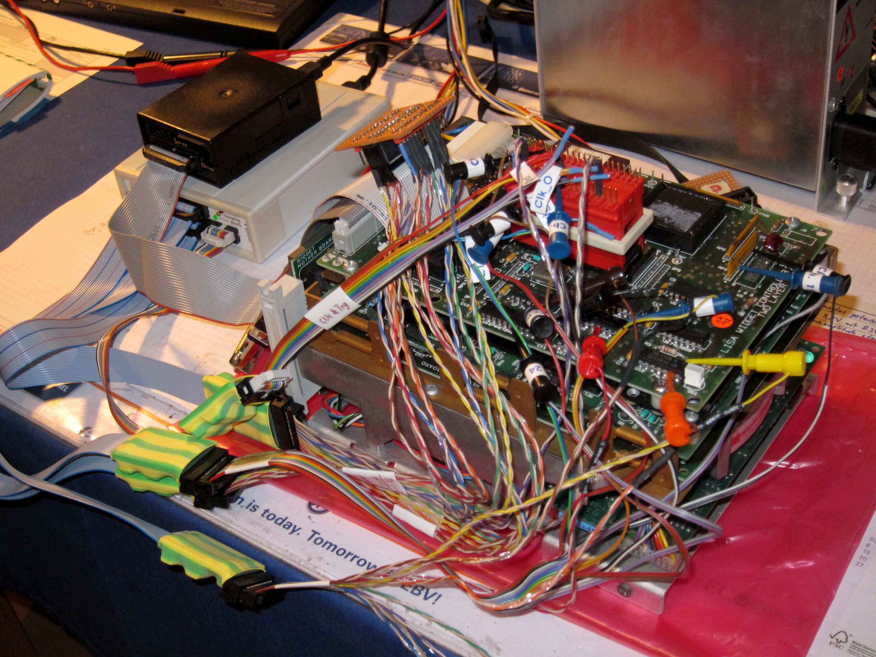 |
Note: if you use a Lisa power supply to power a Widget without Lisa, as I do in the photos above, connect some additional load to the 5 V line. Minimum load requirement is 4 A on the +5 V and 350 mA on the +12 V rail. Widget takes 700 mA at 5 V and 0.75 to 2.0 A at 12 V. I have used an active dummy load set to 3 A (the upper white box above the lamp) to dissipate the remaining power, but some resistors or lightbulbs would also do. Or a Lisa ;-)
Let's start with something simple. We read logical block 0x1234 from disk using ProFile Read command 0x00. Widget understands two command sets. The first one is compatible to the older ProFile series, the second one is more sophisticated and supports multi-block transfers and checksums. This is the ProFile style.
Widget is controlled by UsbWidEx. To read the block, we enter
> r1234
 000012346414 --> 00000000
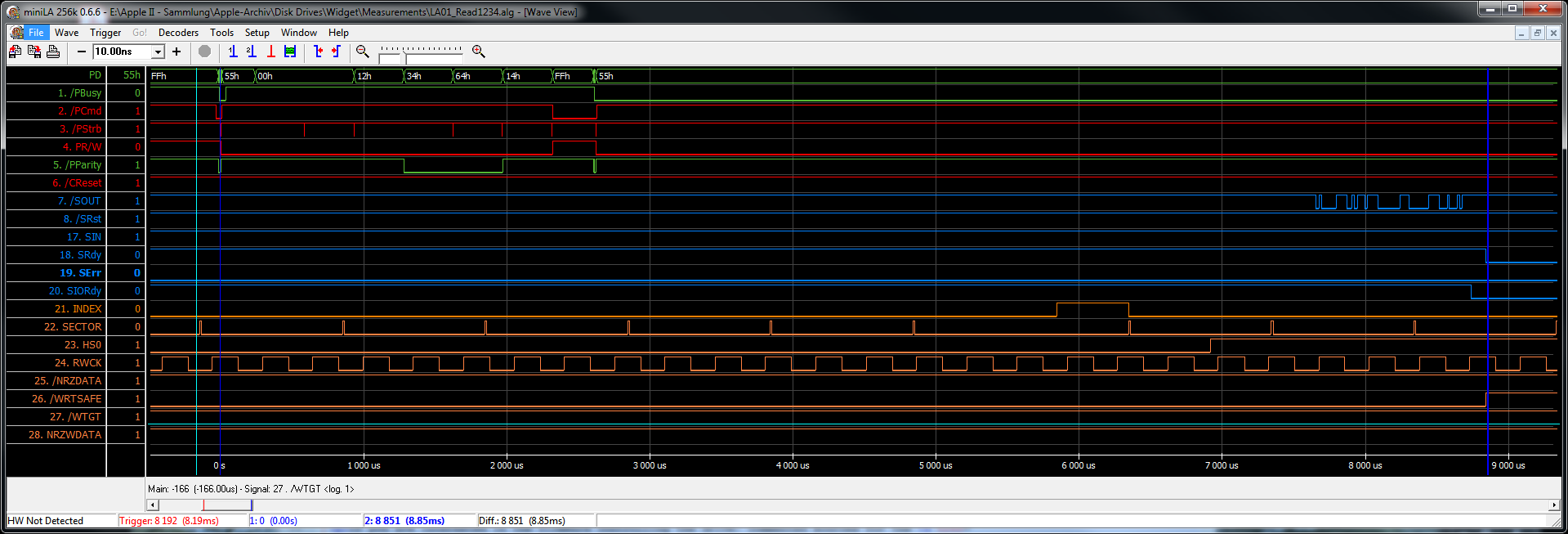
The timing diagrams below shows the whole read cycle. Click on the pictures to enlarge.
First, the read command is transferred from the host (UsbWidEx) into the drive's command buffer. After initial handshake (0x01/0x55), one after another the six bytes 0x00, 0x00, 0x12, 0x34, 0x64 and 0x14 are applied to the bus and /PStrb is pulsed low to write them into the command buffer. This is followed by the secondary handshake (0x02/0x55). The disk is already spinning at nominal 3090 rpm. There is an Index pulse every 19.4 ms and there are 19 Sector pulses spaced 1 ms apart. Opposite to ProFile, Widget is hard-sectored. That means these pulses are generated in hardware by a sensor located at the flywheel at the bottom of the spindle motor. Having received the command, the drive needs about five milliseconds to think about it. The logical block address (LBA) is converted into a physical address (cylinder, head, sector) and it is checked whether the physical block requested is bad and has been spared. In that case, a spare block is used as replacement, whose address is looked up in the Spares Table. Logical block 0x001234 translates into cylinder 007B, head 0, sector 0A.
 |
 |
Unfortunately the heads are currently at cylinder 0235, head 01, therefore a Seek is required. Now the controller sends the command string "0x81, 0xBA, 0x00, 0x80, 0x44" to the servo board (refer to the lower diagram at offset 7.5 ms, command bytes are transferred at 56k7 1N8). This means "seek without ATF offset by -0x1BA tracks". Minus means towards outside of the disk, away from the spindle. Servo commands are always relative, i.e. "go forward 50 tracks", or "go 23 tracks back", they never point to an absolute track number. Even the Recalibrate command goes only somewhere close to track 72. Locating the absolute position and keeping track of it is done by the controller firmware. Having received the command, the servo sets SRdy low and starts the mechanical movement. This is what takes most of the time -- ca. 140 ms. The rising edge of SRdy indicates that the final destination has been reached. Head Select HS0 is switched low for head 0, and reading can begin.
While the disk is spinning, the header of each sector is checked until the desired block has been found. This results in short pulses at the /NRZDATA line. Because of the 1:2 interleave sector 0x0A is the second one after the Index pulse. The controller transfers sector 0x0A into its buffer (the burst on the /NRZDATA line at 163 ms offset) and /PBusy is set high to indicate to the host that data is available. Now four status bytes (0x00 00 00 00 for a successful read) and 532 data bytes are transferred to the host. Each data byte is applied to the bus, then the host sets /PStrb low, reads the byte, and puts /PStrb high again. The rising edge of /PStrb increments the DMA counter on the controller board.
Here is a ZIP file with the raw data in miniLA format.
In this second example we write block 0x2345 to disk using ProFile WriteVerify command 0x02. Again, Widget is controlled by UsbWidEx. We enter
> w2345
 020023456414 --> 00000000
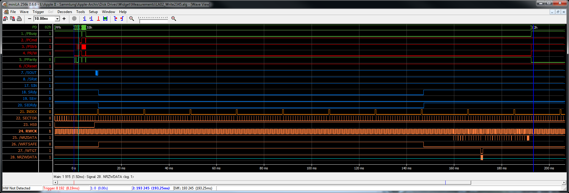
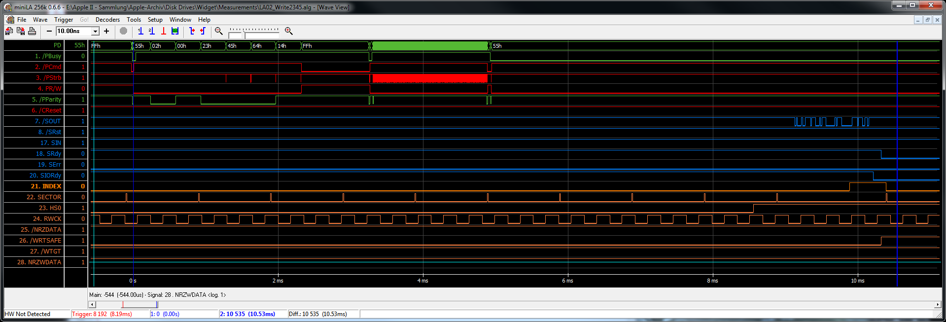
First, the write command is transferred from the host (UsbWidEx) into the drive's command buffer. After initial handshake (0x01/0x55), one after another the six bytes 0x02, 0x00, 0x23, 0x45, 0x64 and 0x14 are applied to the bus and /PStrb is pulsed low to write them into the command buffer. This is followed by the secondary handshake (0x04/0x55), then 532 data bytes are DMAed into the controller's buffer. Data needs to be valid at the rising edge of /PStrb, the falling edge increments the DMA counter on the controller board. Finally a tertiary handshake (0x06/0x55) is done to complete the data transfer. In the meantime the controller has already located the physical sector on the disk. Thanks to DMA the Z8 can work in parallel, so only a fraction of the 5 ms processing period is visible to the host. LBA 0x002345 translates into cylinder 00EE, head 1, sector 0C.
 |
 |
 |
The heads are at their parking position at the inner endstop (cylinder 0x0235), therefore a Seek is required. The controller sends the command string "0x91, 0x47, 0x40, 0x80, 0x67" to the servo board (refer to the center diagram at offset 9 ms), which means "seek with ATF offset by -0x147 tracks, use auto offset". This moves the heads to the desired cylinder and centers them onto the track. During positioning, a correction value ("offset") can be applied by the automatic track following (ATF) circuit on the servo board. This value is chosen automatically so that the maximum signal strength is received, which means the heads are in the middle of the track. During read access, this ATF procedure is skipped because it increases the access time slightly, but during writes it is mandatory to align the new data written precisely with the existing sectors. Having received the command, the servo sets SRdy low and starts the mechanical movement. Ca. 140 ms later the heads have been positioned which is indicated by the rising edge of SRdy. Head Select HS0 is set high for head 1, so we are ready to write. This state is also indicated by the /WRTSAFE signal. It summarizes several hardware conditions like proper voltages, proper disk speed, okay from the servo and from different state machines and so on that are necessary for a successful write operation and acts as a hardware interlock in case of a software fault or sudden power outage.
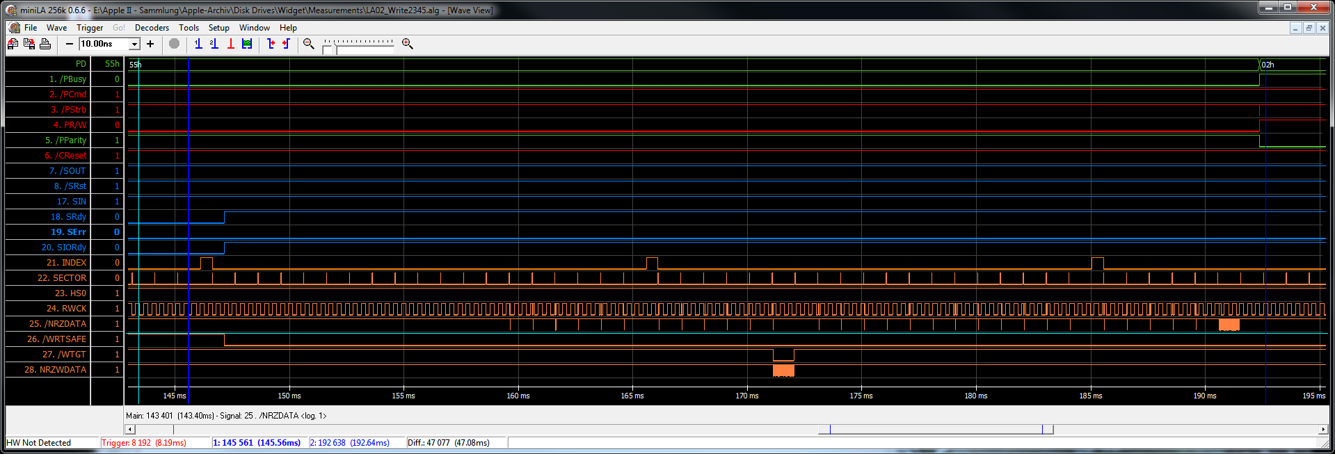
During write operation, only one sector on the disk will be replaced. To be more precise, only the data part of this sector will be replaced, the headers are not modified. Sector headers are never refreshed, so in case one goes bad the corresponding sector will be unuseable until the drive is re-formatted. While the disk is spinning, the header of each sector is checked until the desired block has been found. This results in short pulses at the /NRZDATA line. Due to the 1:2 interleave sector 0x0C is the sixth one after the Index pulse. Immediately after its header has been located, /WTGT (write gate) is switched low to enable the write circuit and 532 bytes of NRZWDATA are written to the disk surface. The controller adds some ECC bytes for error detection and correction, then /WTGT is turned off. Sector data does not use the full space available on disk (one millisecond of track length), there are gaps between sector pulse and header, between header and data, and between data and the next sector pulse. These gaps provide some margin to cover rotational speed tolerances and they give the controller firmware some time to set everything up as required.
A simple Write command (0x01) would be finished here, but the host chose WriteVerify (0x02). Therefore the sector has to be read back and its ECC checksum has to be verified by the controller. Pulses on the /NRZDATA line indicate the address headers, the burst at the sixth sector pulse after Index is the data to be verified. After everything has been completed, /PBusy is set high. Now four status bytes (0x00 00 00 00 for a successful write) are transferred to the host. Each data byte is applied to the bus, then the host sets /PStrb low, reads the byte, and puts /PStrb high again. The rising edge of /PStrb increments the DMA counter on the controller board.
Here is a ZIP file with the raw data in miniLA format. It also includes a second trace with a Write command (0x01, without verify) to block 0x2344. LBA 0x002344 translates into cylinder 00EE, head 1, sector 00. This command has been issued immediately after the previous one, therefore the heads are still on the right track and no seek is required. The whole cycle took only 38 ms which allowed me to use a higher resolution (200 ns timestep instead of 1 µs).
While the original ProFile only supports single block Read (0x00), Write (0x01) and WriteVerify (0x02) commands, Widget is able to handle multi-block commands. This chapter covers SysRead (0x26 0x00). Host is a Lisa 2/10 (internal connector), the traces have been captured during "repair" of a LisaOS 3.1 installation.
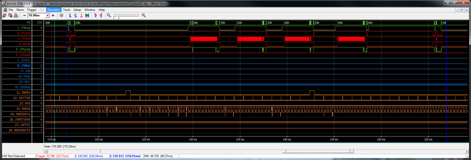
The diagram below shows a SysRead of four blocks. Command bytes sent by the host (Lisa 2/10) were 0x26 00 04 00 00 27 AE. 0x26 0x00 is the command itself, 0x04 the number of blocks to be processed, and 0x0027 is the LBA to start with. The command is followed by a checksum byte (0xAE), which is calculated by adding all command bytes (except the checksum of course) and inverting the result. After the command has been received, the first of the requested blocks is located and read from disk into the controller buffer. Now /PBusy is set high and the host reads four status and 532 data bytes using DMA. When she (the Lisa) has finished, she lowers /PCmd and a tertiary handshake (0x22/0x55) takes place. This tells the controller that the next block can be obtained and prepared for transfer. With properly chosen interleave and mapping, the required block is exactly now below the R/W head and can be picked up. This repeats for all blocks to be transferred. The last block is finished by a (0x01/0x55) handshake. Here Lisa sends 0x69 instead of 0x55. This "invalid" response tells the controller to abort any further transactions and go to its idle task (where cyclic selftests are done).
 |
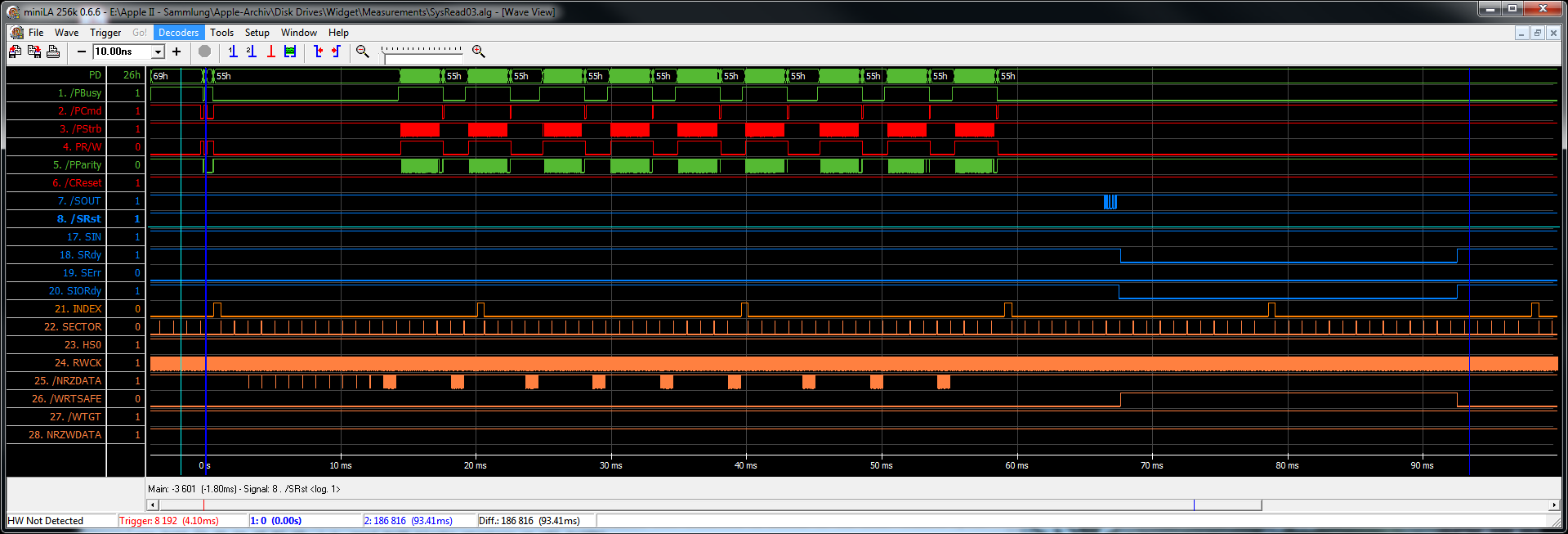
Let's go some more into detail. The traces below are from another SysRead command that transfers 61 blocks to the Lisa. Command bytes are 0x26 00 3D 00 3F B2 AB, i.e. read 0x3D blocks starting at LBA 0x3FB2. Command phase is the same as for any other ProFile or Widget command:
Initial handshake (0x01/0x55):
Host puts command byte on bus, sets /PStb low for 1 µs or more, then high again. Host repeats this for each command byte to be sent.
    0x26 00 3D 00 3F B2 AB 	SysRead 0x3D blocks starting at 0x003FB2
   				0xAB is checksum (inverted sum of all cmd bytes)
Secondary handshake (0x22/0x55):
After the secondary handshake Widget performs the LBA to CHS translation and sends a seek command to the servo subsystem to move its heads to the desired track. In this case no seek is necessary because we already are on the required cylinder. While the disk is spinning, each address header is checked until the requested sector has been found. Here we are looking for sector 0x06, the 13th after index pulse. One disk revolution takes approximately 19.4 ms, that means there is one sector per millisecond. After the sector has been found, data is read into the controller's buffer.
 |
 |
 |
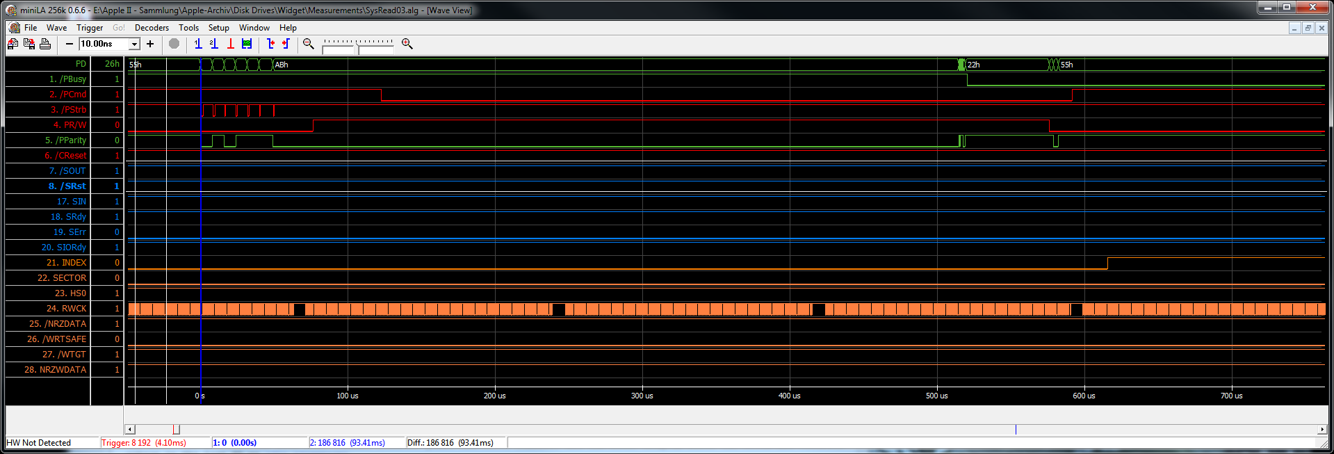
Host reads four status bytes and 532 data bytes from the drive:
Sequence repeats from step 3. (secondary handshake 0x22/0x55) until all blocks have been transferred to the host.
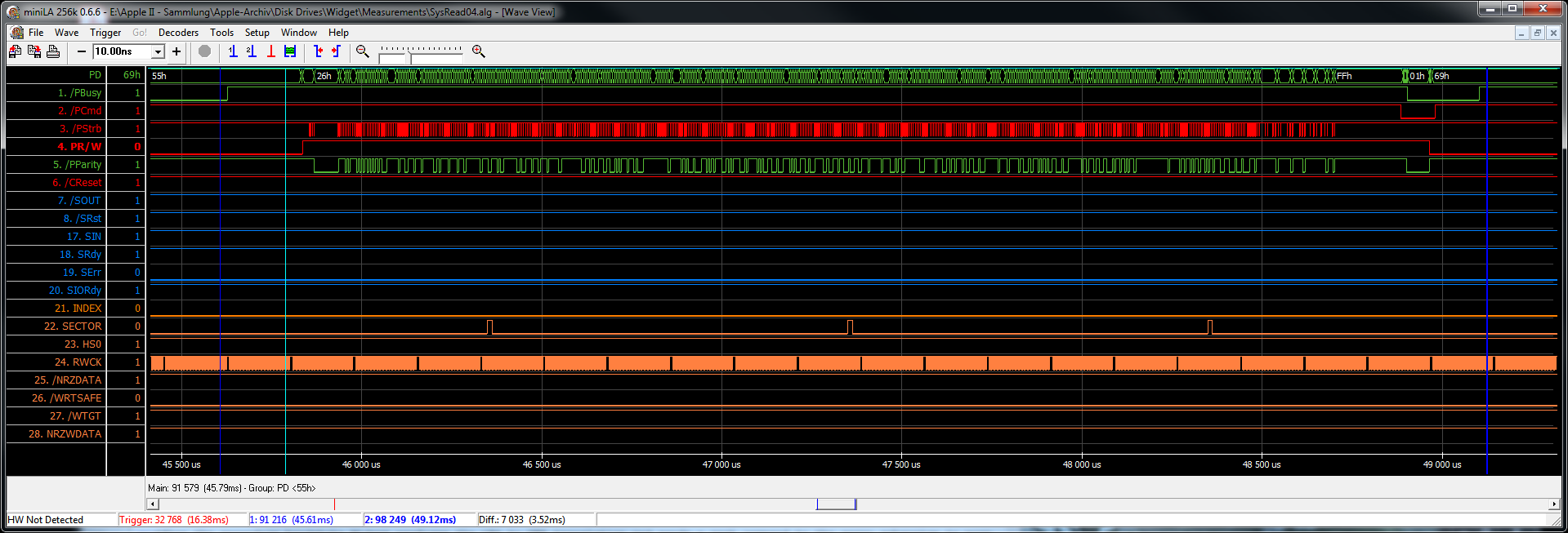
Transferring one block to the host (from /PBusy high / data available to /PCmd high / secondary handshake done) takes approximately 3.4 ms. That means the disk has moved forward by three and a half sectors. With a properly chosen interleaving scheme (1:5) now the the next block is immediately approaching the R/W head and can be copied into the controller buffer. This 1:5 block interleave results from a combination of the 1:2 sector interleave applied during formatting and the 1:8 logical-to-physical interleave map stored in the spares table. The sector interleave specifies the order of the sectors on the disk, the interleave map defines the relationship between logical blocks and disk sectors.
Final handshake:
Sending 0x69 instead of 0x55 switches the drive into idle task. Otherwise it would wait for the next command until timout occurs (Pro- and IDEfile always wait for timeout).
Here is a ZIP file with the raw data in miniLA format. The file contains four traces. The first one, SysRead01, comes from the "Lisa is locating any attached disks" step of the LisaOS 3.1 installation. It has been captured with 1 µs timestep which is too slow to show any details of a Lisa 2/10 access. However, it includes three SysRead and one SysWrite command and gives a good overview. The other three traces have 500 ns timebase. SysRead02 and SysRead03 show the beginning of a sequence, SysRead04 includes the end of one command and the beginning of the next one.
Note: There are some timing differences between Apple ///, Lisa 2/5, Lisa 2/10, Lisa Parallel Card and UsbWidex, and there are even some differences depending on the software used (Bootrom, LisaOS, BLU, ...) Timing is not critical as long as all states are in the correct order. Lisa 2/5 and the Parallel Card are slower than Apple /// and Lisa 2/10 (internal connector). Their /PStrb pulse is 4 µs wide, for the faster devices it is 1 µs. Any drive, emulator, or whatever should be prepared for the faster timing.
Writing the handshake byte (0x55) to the bus is sometimes accompanied by a /PStrb pulse, and sometimes this pulse is missing. Lisa Boot ROM generates it, LisaOS does not. In the drive, $55 is checked by just reading the data bus. There is no DMA cycle, so the /PStrb clock is not needed.
Analogous to SysRead, Widget supports a SysWrite command (0x26 0x01) that allows multi-block writes. The trace discussed here has been captured while the LisaOS 3.1 installer was preparing the drive, i.e. initializing it before the system files are copied. As before, host is a Lisa 2/10. Command string is 0x26 01 7F 00 00 87 D2, which means write 0x7F blocks starting at LBA 0x0087. The following diagram shows the command phase and the transfer of the first 18 blocks, before a Seek to the next track is required.
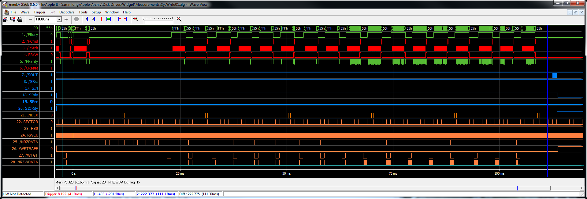 |
In detail, the SysWrite workflow looks like this:
Initial handshake (0x01/0x55):
Host puts command byte on bus, sets /PStb low for 1 µs or more, then high again. Host repeats this for each command byte to be sent.
    0x26 01 7F 00 00 87 D2 	SysWrite 0x7F blocks starting at 0x000087
   				0xD2 is checksum (inverted sum of all cmd bytes)
Host puts data byte on bus, sets /PStb low for 1 µs or more, then high again. Host repeats this for each of the 532 data bytes to be written.
Secondary handshake (0x23/0x55):
After the secondary handshake Widget performs the LBA to CHS translation and sends a seek command to the servo subsystem to move its heads to the desired track. In this case no seek is necessary because we already are on the required cylinder. While the disk is spinning, each address header is checked until the requested sector has been found. Here we are looking for sector 0x05, the 11th after index pulse. One disk revolution takes approximately 19.4 ms, that means there is one sector per millisecond. After the sector has been found, /WTGT (write gate) is switched low and data is written to the disk. Only the data area of the sector is overwritten, not the header.
 |
 |
 |
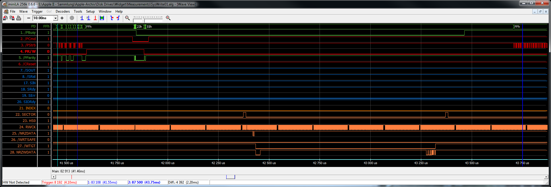
After sector has been written, drive sets /PBusy high
Sequence repeats from step 3. (transfer of 532 data bytes) until all blocks have been transferred to the drive.
Transferring one block to the drive (from /PBusy high / waiting for data to /PCmd high / secondary handshake done) takes approximately 3.4 ms. That means the disk has moved forward by three and a half sectors. With a properly chosen interleaving scheme (1:5) now the the next block is immediately approaching the R/W head and can be written. This 1:5 block interleave results from a combination of the 1:2 sector interleave applied during formatting and the 1:8 logical-to-physical interleave map stored in the spares table. The sector interleave specifies the order of the sectors on the disk, the interleave map defines the relationship between logical blocks and disk sectors.
Tertiary handshake (0x27/0x55):
Host reads four status bytes from the drive:
Final handshake:
Sending 0x69 instead of 0x55 switches the drive into idle task. Otherwise it would wait for the next command until timout occurs (Pro- and IDEfile always wait for timeout).
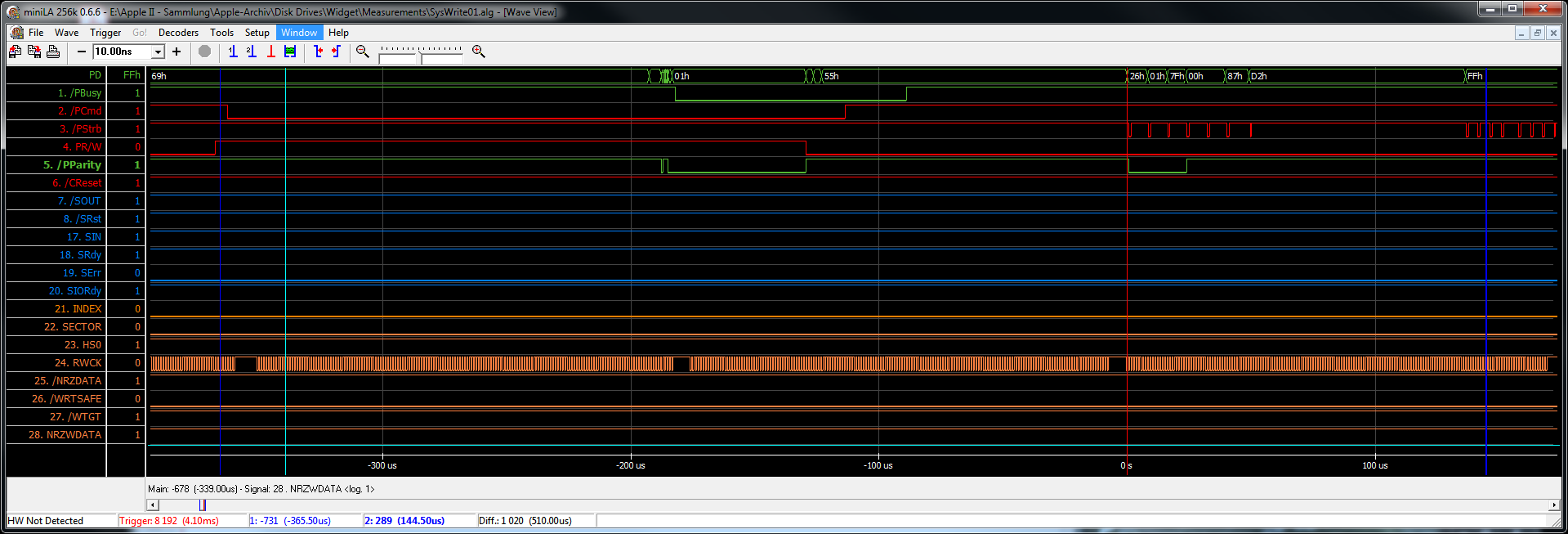
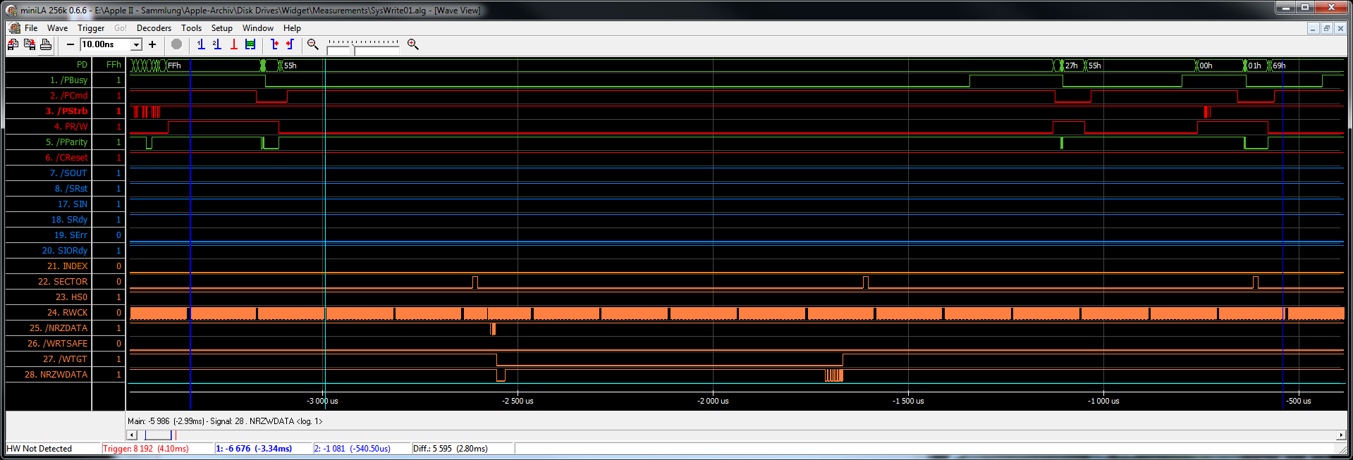
Here is a ZIP file with the raw data in miniLA format. The file contains three traces with 500 ns timebase. All were captured while LisaOS was initializing the drive (high-level formatting). Each of them show the end of the previous write operation and the beginning of a new one, including transfer of data blocks. SysWrite 01 and SysWrite03 end with a seek to the next track while SysWrite02 contains a head change (which costs a full disk revolution, 19.4 ms).
In addition to the two sets of Read/Write/Verify commands, Widget supports 20 Diagnostic commands. These include status reporting, servo control, low-level format and surface scan, spares table management, and low-level read/write access to physical blocks (cylinder/head/sector). All of them are accessible by UsbWidEx or on a Lisa running NeoWidEx. Shown below is the sequence of the Format Track command. Host is UsbWidEx.
Before a track can be formatted, the heads have to be positioned using the Seek command. This includes side select, i.e. setting the HS0 line. After command transfer (0x18 0F 00 01 F0 78 3C 1E 15) and primary handshake (0x11/0x55) the controller waits for the next Index pulse. At the falling edge, the write gate is opened (/WTGT low) while the input of the MFM encoder is held at low level. Due to the MFM enconding this results in an 1T AC signal at the write head which erases any previous data. During the next disk revolution, the odd sectors are written. Each sector starts at the rising edge of a Sector pulse and consists of a header gap, six header bytes, a data gap, 532 data bytes plus eight checkbytes, and an end gap. The header contains the coordinates of the sector: MSB and LSB of cylinder , head and sector number. During read/write operations it is compared to a template with the data of the requested sector, and if both match the read/write process is started. This is a very time-critical sequence, therefore it is done by hardware inside the controller ASIC.
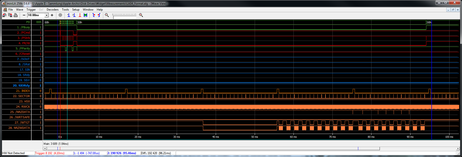 |
The number of the first sector after Index is defined by the Offset parameter in the Format command. Default is zero, but any value between 0 and 18 can be chosen. For the following sectors, the number is calculated by adding a constant increment to the previous sector number. If the result is above 19, 19 is subtracted. The increment depends on the Interleave parameter specified in the Format command:
   parameter    0    1    2    3    4    5    6
   interleave  1:1  1:2  1:3  1:4  1:5  1:6  1:7
   increment    2    1    7   10    8   13    3
So for an 1:3 interleave this results in the sequence 0, ., 7, ., 14, ., 2, ., 9, ., 16, ., 4, ., 11, ., 18, ., 6. During the third disk revolution, the even sectors are written. The sequence continues with ., 13, ., 1, ., 8, ., 15, ., 3, ., 10, ., 17, ., 5, ., 12, .. Both matched together results in the desired interleaving: 0, 13, 7, 1, 14, 8, 2, 15, 9, 3, 16, 10, 4, 17, 11, 5, 18, 12, 6.
Usually Widget is formatted with 1:2 interleave, but the above example is more descriptive.
Here is a ZIP file with the raw data of this trace in miniLA format.
The next trace has been captured during a Scan command. After command transfer (0x12 13 DA) and initial handshake (0x15/0x55) each sector on each track is read and checked for a valid ECC. Scan starts at cylinder 0, head 0. Here, the last access was a Read 0x000000, therefore the heads are already at cylinder 0 and no seek is required. Sectors are read in logical order, i.e. interleaving is applied. Therefore it takes two disk revolutions to check the whole track before HS0 is toggled to switch to the other side. After both sides have been scanned a Seek is taken to the next track.
Bad blocks encountered during Scan are recorded in the spares table. If data can be recovered, the block will be replaced by a spare. Otherwise it will be marked as "bad" until it is written the next time. If this write succeeds, the block is removed from the spares table and considered repaired. If it fails, it is permanently replaced by a spare block.
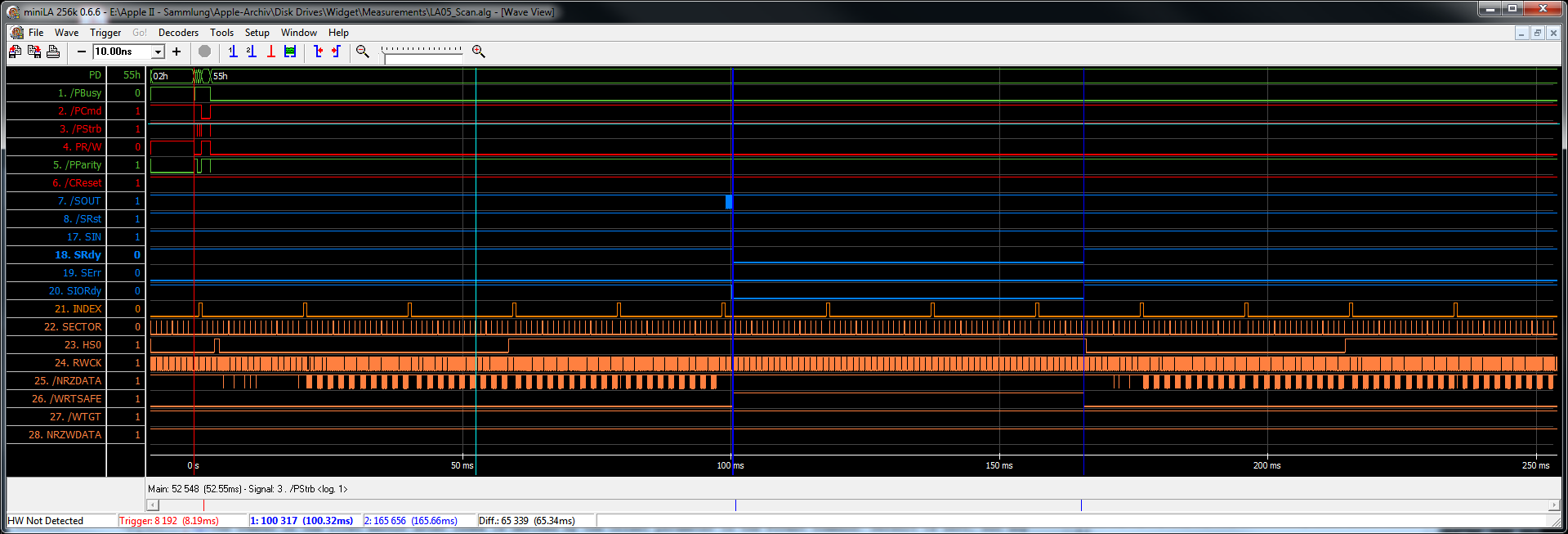 |
Here is a ZIP file with the raw data of this trace in miniLA format.
The last example shows a "Diagnostic Read including Header" of sector 3. Like Format Track, this command does not include positioning the heads, so a Seek to the desired cylinder and head has to be done before. After command transfer (0x13 0A 03 DF) and initial handshake (0x0C/0x55) the controller waits for the next Index pulse. After that, Sector pulses are counted until the position of the requested sector has been reached. Then everything that comes across the read head is transferred into the controller buffer. Headers are not checked, the sector is located by its physical position on the track only. Now /PBusy is set high and four status bytes followed by the buffer contents are be transferred to the host.
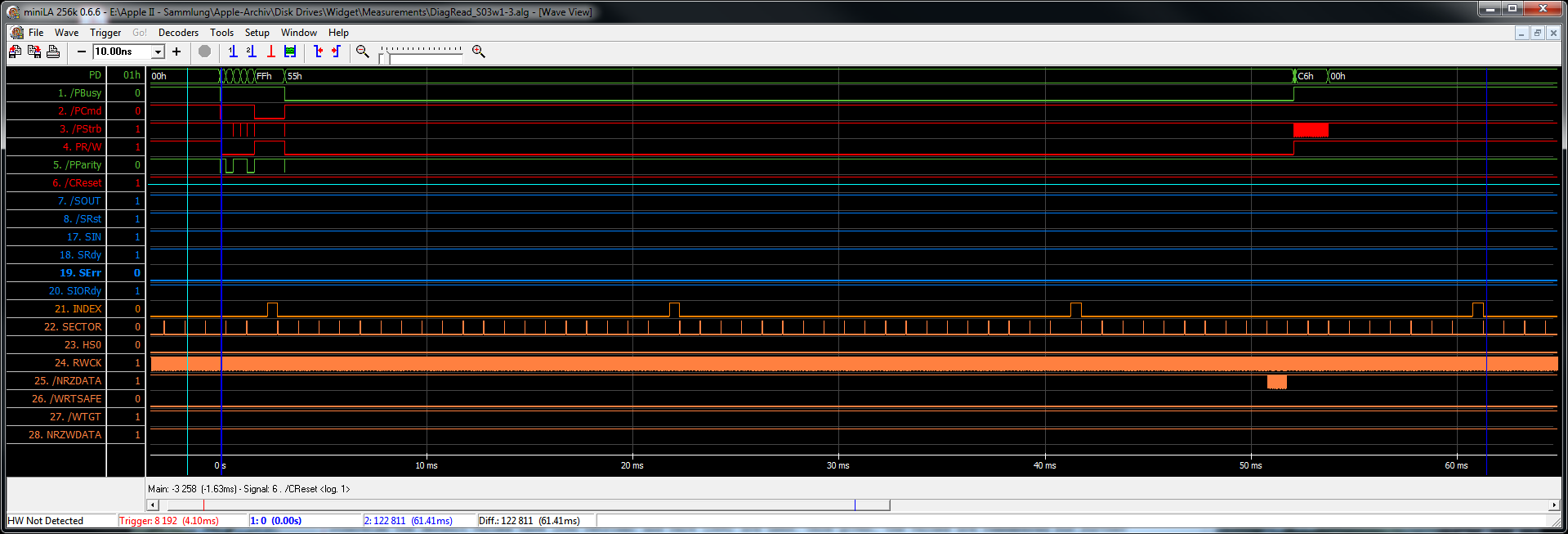 |
Note that the Widget used to capture this trace has been formatted with 1:3 interleaving. Therefore sector 3 is not the 7th after Index as you would expect for the regular 1:2 interleave, but the 10th.
Raw data of an otherwise empty block looks like this:
> t3
 130A03DF --> 00000000
> d

Command Buffer:

00000000 00000000 00000000 00000000

Data Buffer:

0000: 006903FF96FC0000 0000000000C6C6C6 .i.ÿ-þ.......ÆÆÆ
0010: C6C6C6C6C6C6C6C6 C6C6C6C6C6C6C6C6 ÆÆÆÆÆÆÆÆÆÆÆÆÆÆÆÆ
0020: C6C6C6C6C6C6C6C6 C6C6C6C6C6C6C6C6 ÆÆÆÆÆÆÆÆÆÆÆÆÆÆÆÆ
0030: C6C6C6C6C6C6C6C6 C6C6C6C6C6C6C6C6 ÆÆÆÆÆÆÆÆÆÆÆÆÆÆÆÆ
0040: C6C6C6C6C6C6C6C6 C6C6C6C6C6C6C6C6 ÆÆÆÆÆÆÆÆÆÆÆÆÆÆÆÆ
0050: C6C6C6C6C6C6C6C6 C6C6C6C6C6C6C6C6 ÆÆÆÆÆÆÆÆÆÆÆÆÆÆÆÆ
0060: C6C6C6C6C6C6C6C6 C6C6C6C6C6C6C6C6 ÆÆÆÆÆÆÆÆÆÆÆÆÆÆÆÆ
0070: C6C6C6C6C6C6C6C6 C6C6C6C6C6C6C6C6 ÆÆÆÆÆÆÆÆÆÆÆÆÆÆÆÆ
0080: C6C6C6C6C6C6C6C6 C6C6C6C6C6C6C6C6 ÆÆÆÆÆÆÆÆÆÆÆÆÆÆÆÆ
0090: C6C6C6C6C6C6C6C6 C6C6C6C6C6C6C6C6 ÆÆÆÆÆÆÆÆÆÆÆÆÆÆÆÆ
00A0: C6C6C6C6C6C6C6C6 C6C6C6C6C6C6C6C6 ÆÆÆÆÆÆÆÆÆÆÆÆÆÆÆÆ
00B0: C6C6C6C6C6C6C6C6 C6C6C6C6C6C6C6C6 ÆÆÆÆÆÆÆÆÆÆÆÆÆÆÆÆ
00C0: C6C6C6C6C6C6C6C6 C6C6C6C6C6C6C6C6 ÆÆÆÆÆÆÆÆÆÆÆÆÆÆÆÆ
00D0: C6C6C6C6C6C6C6C6 C6C6C6C6C6C6C6C6 ÆÆÆÆÆÆÆÆÆÆÆÆÆÆÆÆ
00E0: C6C6C6C6C6C6C6C6 C6C6C6C6C6C6C6C6 ÆÆÆÆÆÆÆÆÆÆÆÆÆÆÆÆ
00F0: C6C6C6C6C6C6C6C6 C6C6C6C6C6C6C6C6 ÆÆÆÆÆÆÆÆÆÆÆÆÆÆÆÆ
0100: C6C6C6C6C6C6C6C6 C6C6C6C6C6C6C6C6 ÆÆÆÆÆÆÆÆÆÆÆÆÆÆÆÆ
0110: C6C6C6C6C6C6C6C6 C6C6C6C6C6C6C6C6 ÆÆÆÆÆÆÆÆÆÆÆÆÆÆÆÆ
0120: C6C6C6C6C6C6C6C6 C6C6C6C6C6C6C6C6 ÆÆÆÆÆÆÆÆÆÆÆÆÆÆÆÆ
0130: C6C6C6C6C6C6C6C6 C6C6C6C6C6C6C6C6 ÆÆÆÆÆÆÆÆÆÆÆÆÆÆÆÆ
0140: C6C6C6C6C6C6C6C6 C6C6C6C6C6C6C6C6 ÆÆÆÆÆÆÆÆÆÆÆÆÆÆÆÆ
0150: C6C6C6C6C6C6C6C6 C6C6C6C6C6C6C6C6 ÆÆÆÆÆÆÆÆÆÆÆÆÆÆÆÆ
0160: C6C6C6C6C6C6C6C6 C6C6C6C6C6C6C6C6 ÆÆÆÆÆÆÆÆÆÆÆÆÆÆÆÆ
0170: C6C6C6C6C6C6C6C6 C6C6C6C6C6C6C6C6 ÆÆÆÆÆÆÆÆÆÆÆÆÆÆÆÆ
0180: C6C6C6C6C6C6C6C6 C6C6C6C6C6C6C6C6 ÆÆÆÆÆÆÆÆÆÆÆÆÆÆÆÆ
0190: C6C6C6C6C6C6C6C6 C6C6C6C6C6C6C6C6 ÆÆÆÆÆÆÆÆÆÆÆÆÆÆÆÆ
01A0: C6C6C6C6C6C6C6C6 C6C6C6C6C6C6C6C6 ÆÆÆÆÆÆÆÆÆÆÆÆÆÆÆÆ
01B0: C6C6C6C6C6C6C6C6 C6C6C6C6C6C6C6C6 ÆÆÆÆÆÆÆÆÆÆÆÆÆÆÆÆ
01C0: C6C6C6C6C6C6C6C6 C6C6C6C6C6C6C6C6 ÆÆÆÆÆÆÆÆÆÆÆÆÆÆÆÆ
01D0: C6C6C6C6C6C6C6C6 C6C6C6C6C6C6C6C6 ÆÆÆÆÆÆÆÆÆÆÆÆÆÆÆÆ
01E0: C6C6C6C6C6C6C6C6 C6C6C6C6C6C6C6C6 ÆÆÆÆÆÆÆÆÆÆÆÆÆÆÆÆ
01F0: C6C6C6C6C6C6C6C6 C6C6C6C6C6C6C6C6 ÆÆÆÆÆÆÆÆÆÆÆÆÆÆÆÆ
0200: C6C6C6C6C6C6C6C6 C6C6C6C6C6C6C6C6 ÆÆÆÆÆÆÆÆÆÆÆÆÆÆÆÆ
0210: C6C6C6C6C6C6C6C6 C6C6C6C6C6C6C6C6 ÆÆÆÆÆÆÆÆÆÆÆÆÆÆÆÆ
0220: C6A3FF0000000000 0000000000000000 Æ£ÿ.............
The first six bytes are the sector header. 0x00 69 means track 0x0069, 0x03 means sector 3 on head 0. Bit 6+7 of this byte encode the head number, so sector 3 on head 1 would be 0x43. The next three bytes contain the same information, but inverted. After seven gap bytes (the zeros) 532 bytes of user block data (0xC6) follow. This is the default data pattern after formatting. The last two bytes, 0xA3 FF, are the CRC checksum. There is also an ECC checksum, but this is not copied into the controller buffer and therefore not visible here.
Here is a ZIP file with the raw data of this trace in miniLA format.
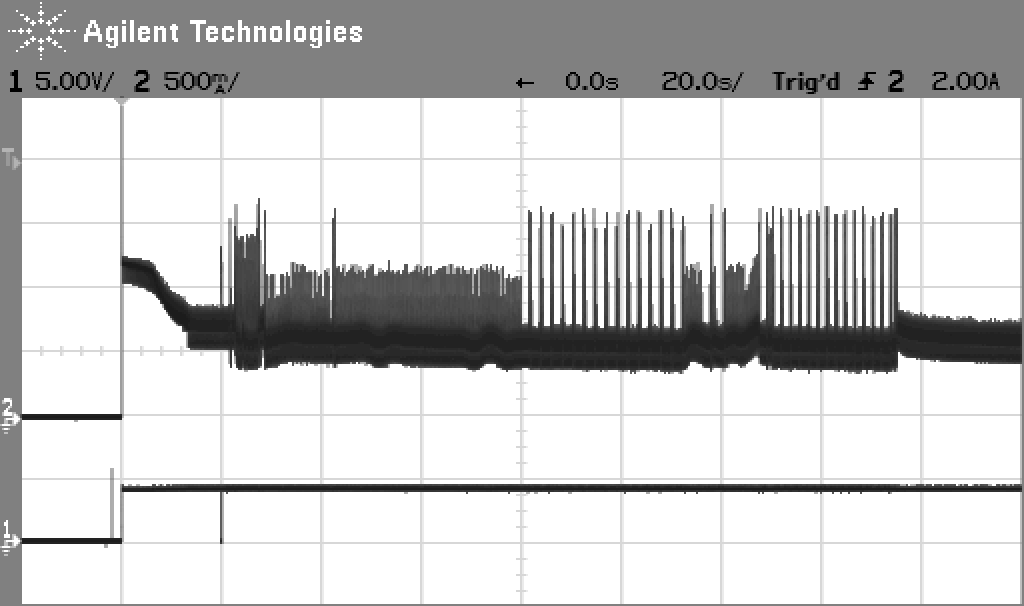
This chapter contains representations of the temporal course of the supply current flow into an Apple Widget Hard Disk. These measurements have been taken with a HP 54622D oscilloscope with Agilent N2783A current clamp probe.
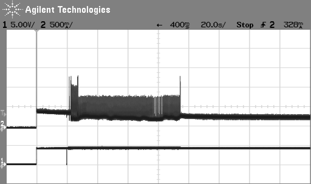
The diagram below on the left shows the current consumption during startup. Upper trace is current on both +12 V rails (Motor and Logic), lower trace is /SRst (servo reset). After power has been applied, the motor spins up. Inrush current is approximately 1.25 A, going down to 700 mA when the spidle accelerates. After 20 seconds, when the motor is up to its nominal speed of 3090/min, /SRst is pulsed low. This servo reset pulse releases the head brake solenoid, you hear a loud "click". Now the drive performs a quick selftest (you hear "squeak-squeak") before a Scan is done. During scan all sectors are read and checked, bad sectors are recorded in the spares table. You hear a ticking sound while the LED is flashing, interrupted by a "squeak-squeak" for each sparing action. Sparing is clearly visible in the current flow -- here the current increases up to 1.6 A due to the wide head movement.
 |
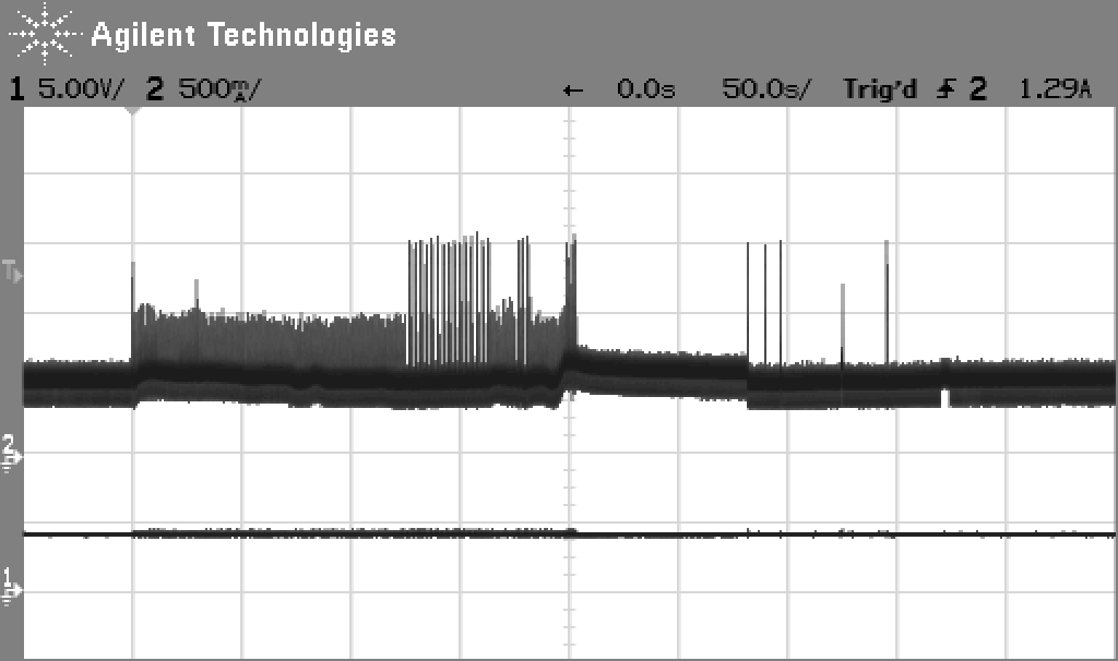 |
On the right, we see a linear read scan, this goes from the first time division to the center (200 seconds). Here UsbWidEx reads each block in successive order. Its shape is very similar to the one obtained during startup. The three needles with an amplitude of 1.5 A result from three single read accesses to blocks located far away from each other -- this results in maximum current consumption. The smaller peak is a Recal (move to track 72), and the last one is a Park comand (move to the inner endstop).
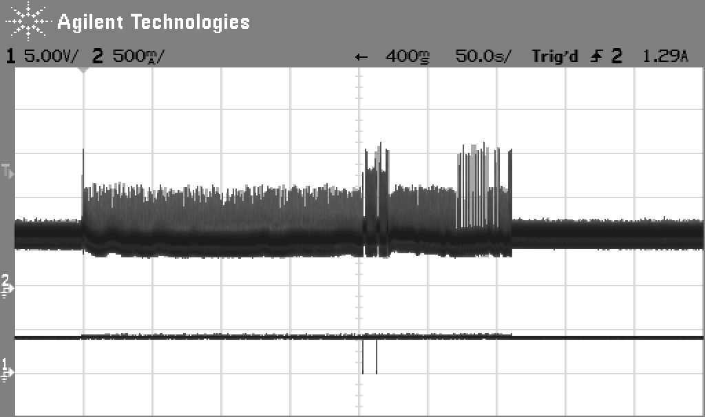
Below on the left, the current consumption on the +12 V rails during a lowlevel format is shown. This curve can be divided into three sections: after initial recalibration (1.6 A peak) for the first 200 seconds each track is formatted. After that, the drive is reset, we see the /SRst pulse and some action from the internal selftest. Now the spares tables are written, and the drive is reset again. After a second selftest the scan starts. During the scan some bad blocks are encountered, which are recorded into the spares table -- these are the peaks in the last part of the pattern.
 |
 |
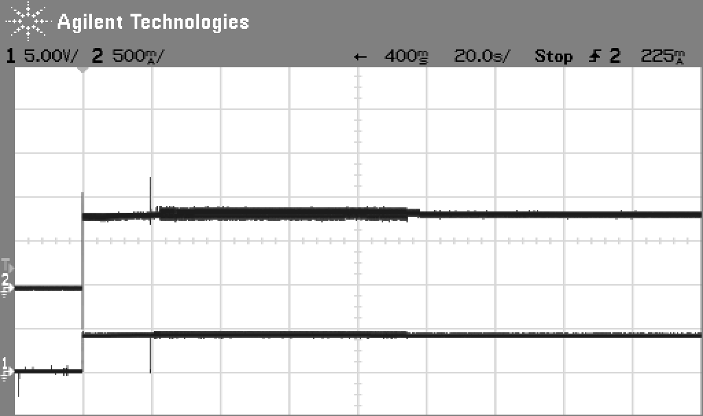
The diagram on the right shows another startup sequence. This has been measured on a "good" drive without bad blocks. There is no irregular head movement in the 70 second scan phase.
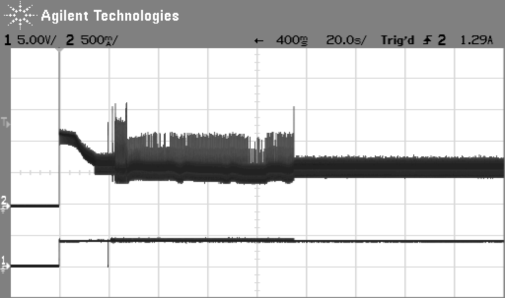
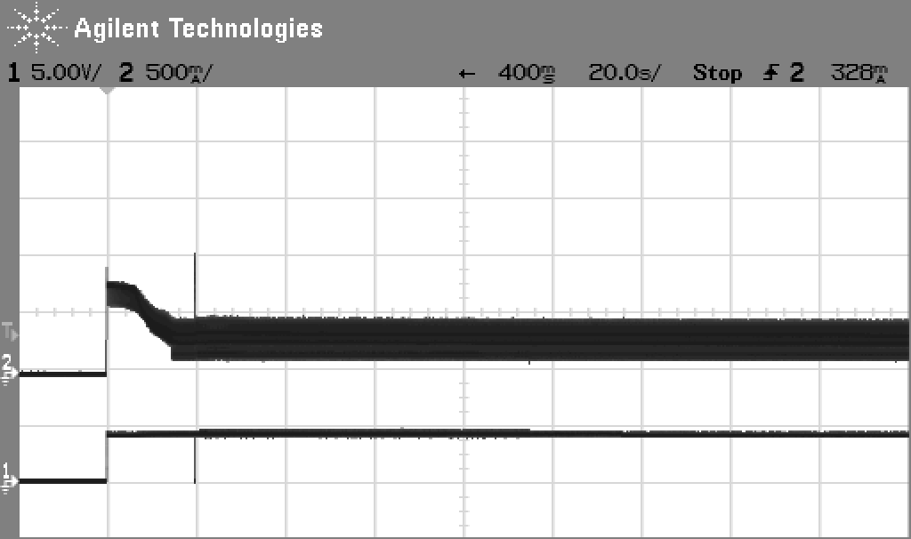
Finally, these three diagrams show the current flow during startup on the +12 V Motor, +12 V Logic and +5 V rails separately. As usual, click on the images for full size!
 |
 |
 |
Motor current is less than 500 mA in steady state, with a lot of ripple from commutation. The spindle motor is a four phase brushless DC design. Servo + Logic current is approximately 250 mA in steady state with peaks up to 1.2 A during seek activity. Current on the +5 V rail is almost constant at 700 mA.
To operate a Widget outside the Lisa's drive cage, use a power supply with at least 2 A current capability on the +12 V rails and at least 1 A on the +5 V rail. -12 V is only used for the amplifiers, so less than 0.5 A are enough. Motor and Logic supply should be separated from each other, i.e. use two different +12 V wires.
UsbWidex is copyright (c) by Dr. Patrick Schäfer, 2014
Apple, Lisa, ProFile, Widget and the ProFile communications protocol are (c) by Apple Computer Inc.
----> Back to the UsbWidEx page
----> Back to my home page