


Analog Tuner
1980
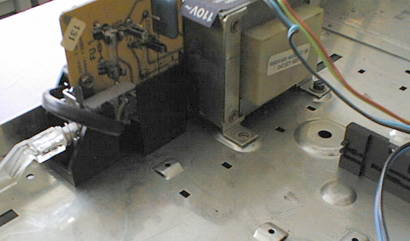
The CT 10 could be described as the TT 350's successor in the 1980's 'slim line' devices. Except for the cassette deck, these devices all had a cabinet about half in height than the one of their predecessors, and all cabinets were entirely made of metal, in contrast to the plastic frames present e.g. in the TT 350. Otherwise, the CT 10 is rather similar to the TT 350: a simple analog tuner without many features, and it contains in fact the same boards as the TT 350. And though the cabinet's size was halved, it is still mostly empty...
Variable Muting Level, Automatic Fine Tuning, Exact Tuning Indicator
(taken from the service manual)
| Wave Ranges: | FM = 87.6 ... 108 MHz |
| MW = 518 ... 1610 kHz | |
| LW = 148 ... 325 kHz | |
| Circuits: | AM 5 / FM 9 |
| Intermediate Frequency: | AM 460 kHz / FM 10.7 MHz |
| IF Bandwidth: | AM 4.5 kHz / FM 170 kHz |
| Sensitivity: | FM 2.5 µV Mono / 5 µV Stereo |
| (S/N = 26 dB, 1000 Hz, 40 kHz Modulation, 240 Ohm | |
| Distortion Factor FM: | < 0.5 % Mono / < 0.6% Stereo |
| (1 kHz, 40 kHz Modulation) | |
| Extraneous Voltage Ratio FM: | > 62 dB Mono / > 59 dB Stereo |
| (acc. to DIN 45 500, Sht 2) | |
| Signal / Noise Ratio FM: | > 61 dB Mono / > 55 dB Stereo |
| (acc. to DIN 45 500, Sht 2) | |
| Pilot Tone Suppression: | > 53 dB (acc. to DIN 45 500, |
| Sht. 2/8, AF and TB) | |
| Channel Separation: | > 38 dB / 1 kHz |
| Tuning Aids: | Field strength indicating element |
| for AM/FM with LEDs, stereo indicator, | |
| exact tuning indicator | |
| Semiconductors: | 5 Integrated Circuits |
| 13 Transistors | |
| 12 LEDs | |
| 7 Diodes | |
| 1 Mains Rectifier | |
| Mains Voltage: | 220/110 Volts at 50/60 Hz |
| Fuses: | Mains 220 V 1 x T 125 mA |
| 110 V 2 x T 125 mA | |
| Secondary T 315 mA | |
| Dimensions: | 460 x 80 x 350 mm |
The CT10 suffers from the same, simple failure as may other Telefunken devices in that era: a broken mains switch! Symptoms are that the device cannot be turned on or off any more, or a power switch button that doesn't move at all. The problem is the the 'ball pen' mechanics consist of a piece of metal moving in a plastic bearing, and the plastic wears out over time. Replacing the switch is not that a problem, given you can get one that fits precisely - you need a variant that has both pins on the underside (for soldering into the PCB) and soldering contacts on the upper side (for connecting the power cord).
(taken from the service manual)
| Cabinet Parts | ||
|---|---|---|
| 501 | 309 796 047 | cabinet, brown |
| 502 | 309 796 049 | cabinet, black |
| 503 | 309 833 633 | front cover, brown |
| 504 | 309 833 634 | front cover, champagne |
| 505 | 309 833 577 | cover for indicator |
| 506 | 309 710 224 | dial, brown |
| 507 | 309 833 635 | dial cover |
| 508 | 309 802 124 | control knob for tuning |
| 509 | 309 802 115 | control knob for range |
| 510 | 309 802 125 | control knob for muting |
| 511 | 309 800 131 | push button knob |
| 512 | 309 921 921 | mains switch rod with knob |
| Electrical Parts | ||
| BS 5108 | 349 362 015 | AM-FM-AF-O/P and range rotary switch module |
| BS 5537 | 309 310 149 | mains transformer with fuse board |
| BS 5606 | 349 350 925 | FM mixing unit with AM tuning capacitor |
| BS 5730 | 349 395 022 | LED indicator (field strength) |
| BS 5775 | 309 362 019 | switch board (type of operation) |
| D 1 | 309 327 022 | LED FLV 110 red |
| FU 1 | 309 627 946 | fuse T 125 mA |
| LA 1/2 | 309 621 960 | dial lamp 6-7 V/300 mA |
| R 1 | 309 500 073 | film variable resistor, 10 KOhm |
| S 3/4 | 309 635 915 | push switch mono/AFC |
| 513 | 309 630 023 | mains switch |
| 514 | 309 695 935 | power cable with plug |
| 515 | 309 601 955 | FM antenna |
| 516 | 309 603 807 | AM antenna |
| AM-FM Switch Module | ||
| BS 5108 | 349 362 015 | AM-FM-AF-O/P and range rotary switch module |
| BU 101/S 101 | 309 670 923 | AM antenna socket with switch |
| BU 102 | 309 670 927 | combined antenna socket |
| BU 103 | 309 672 801 | DIN socket, 5 contacts |
| BU 104/105 | 309 679 503 | Cinch socket |
| C 113 | 309 450 605 | disc trimmer N 750 10/40/250 V |
| C 177 | 309 414 737 | Al-electr. cap. 2200 µF/40 V |
| D 104/105/106/ | 309 325 027 | diode 1 N 4148 |
| 108/109/110 | ||
| FI 101 | 309 103 952 | ceramic filter 10.7 MHz |
| FI 102 | 309 111 802 | band filter |
| FI 103 | 309 103 953 | ceramic resonator 460 kHz |
| FI 104 | 309 220 031 | IF filter coil |
| FI 105/106 | 309 103 948 | ceramic filter 19 kHz/38 kHz |
| FU 101 | 309 627 901 | fuse T 315 mA |
| GR 101 | 309 320 602 | rectifier B 30 C 350/250 KP |
| IC 101 | 309 368 133 | IC TDA 1046 |
| IC 102 | 309 368 094 | IC CA 3089 E |
| IC 103 | 309 368 173 | IC TCA 4500 A |
| IC 104 | 309 368 130 | IC UA 78 GU 1 C |
| L 101 | 309 259 919 | choke |
| L 102 | 309 309 950 | antenna transformer |
| L 103 | 309 250 930 | RF choke 2200 µH |
| L 104 | 309 207 922 | pre-circuit coil MW |
| L 105 | 309 208 911 | pre-circuit coil LW |
| L 106 | 309 259 934 | RF choke |
| L 107/108 | 309 218 922 | oscillator coil LW |
| L 111 | 309 220 083 | filter coil 18 MHz |
| L 112 | 309 220 046 | filter coil 10.7 MHz |
| R 157 | 309 500 071 | variable resistor 5 K/1/0.15 W |
| R 166 | 309 509 401 | variable resistor 10 K/1/0.07 W |
| S 104 | 309 639 003 | rotary switch, 6 positions |
| T 101 | 309 001 238 | transistor BF 441 |
| T 102/103/107/ | 309 001 248 | transistor BC 308 B |
| 109 | ||
| T 104 | 309 001 227 | transistor BF 256 B |
| T 105/106/110 | 309 001 949 | transistor BC 238 B |
| T 108/111/112 | 309 001 241 | transistor BC 238 C |
| 517 | 309 689 904 | IC socket, 16 contacts |
| FM Mixing Unit | ||
| BS 5606 | 349 350 925 | FM mixing unit with AM tuning capacitor |
| C 105/116/122 | 309 400 967 | tuning capacitor |
| C 614 | 309 452 805 | tube trimmer 1.2/10 |
| C 625 | 309 461 703 | Ta-electr. cap. 22 µF/6.3 V |
| D 601 | 309 327 956 | diode SMV 709 |
| D 602 | 309 325 027 | diode 1 N 4148 |
| FI 601 | 309 220 013 | IF filter |
| L 601 | 309 209 930 | FM antenna coil |
| L 602 | 309 209 931 | pre-circuit coil |
| L 603 | 309 219 935 | oscillator coil |
| L 604 | 309 249 171 | intermediate circuit coil |
| L 605 | 309 250 943 | RF choke |
| T 601 | 309 005 007 | transistor 2 SK 55 D |
| T 602/603 | 309 001 933 | transistor BF 241 |
| LED Indicator | ||
| BS 5730 | 349 395 022 | LED indicator (field strength) |
| C 701 | 309 410 655 | Al-electr. cap. 2.2 µF/25 V |
| D 701-710 | 309 327 053 | LED CQY 85 red |
| D 711 | 309 327 022 | LED FLV 110 red |
| IC 701 | 309 368 231 | IC U 254 B |
| IC 702 | 309 368 230 | IC U 244 B |
| 518 | 309 900 292 | diode support, 12-fold |
| Mechanical Parts | ||
| 525 | 309 863 989 | chassis |
| 526 | 309 926 808 | tension roller for cord |
| 527 | 309 981 802 | spring for tension roller |
| 528 | 309 926 715 | cord roller |
| 529 | 309 926 985 | cord disc |
| 530 | 309 926 985 | cord roller |
| 531 | 309 823 015 | pointer |
| 532 | 309 870 925 | dial cord |
| 533 | 309 943 020 | tuning shaft |
| 534 | 309 927 909 | flywheel |
| 535 | 309 943 024 | shaft for range selector |
| 536 | 309 928 904 | clutch for shaft |
| 537 | 309 831 718 | light box |
| 538 | 309 831 719 | diffusor (plastic) |
| 539 | 309 689 929 | lamp socket |
| 540 | 309 900 295 | diode support, 1-fold |
| 541 | 309 653 501 | fuse holder |