

Integrated Amplifier
1981
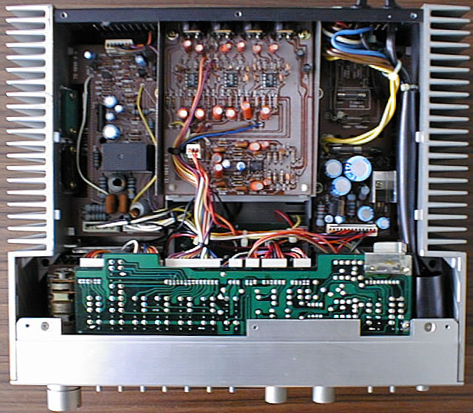
The MA 1 was Telefunken's high-class amplifier offering in the line of Midi-sized (30x30 cm basic area) Hifi components. Compared to its size, it offers a quite respectable output power of 2x50W RMS and almost all features one would expect from an amplifier at that time, including a power level meter with selectable range. It is part of the M 1 component system, and shares the unusual housing concept: the housing is made of an inner frame, and aluminium profiles attached to it make the 'outer skin'. This housing concept is similar to laboratory devices and in contrast to standard housing concepts of Hifi devices at that time, which were based on bended metal sheets. It gives the whole system a very worthy look, and Telefunken won an industry design award for it. But even among the other M 1 components, the MA 1 looks unconventional with its exposed heatsinks on both sides.
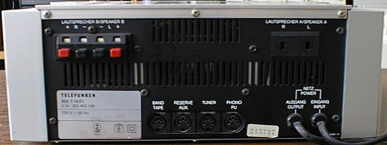
four inputs, tape copy function, loudness, tone controls may be bridged with the defeat switch, noise filter, LED level meters with selectable range, two pairs of speakers may be attached.
(taken from the service manual)
| Nominal Impedance: | 4 Ohms |
| Nominal Output Power: | 2 x 50 W RMS |
| Peak Output Power: | 2 x 80 W |
| Distortion Factor: | 0.1 % at 1 kHz (45 W/4 Ohms), |
| typ. < 0.5 % at 40 W/4 Ohms, 20-16000 Hz | |
| Power Bandwidth: | < 10 Hz ... > 40 kHz for K <= 0.7 % |
| Phono Deemphasis: | acc. to DIN 45 547 |
| Nominal Input Voltages/ | |
| Nominal Input Impedances/ | |
| Overdrive Reserve (4 Ohms): | 180 mV / 470 kOhm / 33 dB (tape) |
| 180 mV / 470 kOhm / 33 dB (aux) | |
| 180 mV / 470 kOhm / 33 dB (tuner) | |
| 1.6 mV / 47 kOhm / 33 dB (phono) | |
| Output Levels at Nominal | |
| Output Power: | 1 mV/kOhm at tape input and 1 V |
| input voltage at aux input | |
| 14.14 V at speaker output (4 Ohms) | |
| 0.42 V at headphone output (8 Ohms) | |
| S/N ratio acc. to DIN 45 500: | > 60 dB at tape/aux |
| > 60 dB at phono | |
| Channel Separation: | > 55 dB at 1 kHz |
| > 40 dB at 10 kHz | |
| Input Separation: | > 80 dB at 1 kHz |
| > 65 dB at 10 kHz | |
| Tone Control: | Bass: +13 to -13 dB at 40 Hz |
| Treble: +11 to -11 dB at 15 kHz | |
| Balance Control: | 0 to -40 dB |
| Noise Filter: | 7 kHz turnover frequency, 12 dB/oct. |
| Semiconductors: | 15 integrated circuits |
| 25 transistors | |
| 28 diodes | |
| 37 LEDs | |
| Mains Supply: | 220/110 V, 50/60 Hz |
| Dimensions: | 298 x 114 x 250 mm |
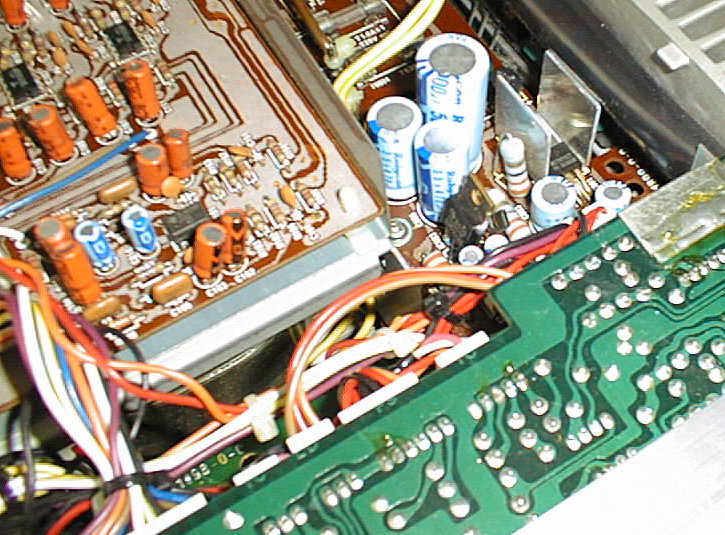
The MA 1 is principally a solid amplifier with discrete power stages. I had so far only one minor failure: a -12V three-terminal voltage regulator, located on the power supply board on the underside. While the +12V regulator has a heatsink, the -12V regulator only supplies the input amplifier board and Telefunken therefore used a 100mA version (78L12, TO-92 housing) without any heatsink. 78xx/79xx regulators however have no SOA protection and are therefore sensitive to overheating, which seemed to have happened to the regulator in this case. I replaced the regulator with a standard 7912 1000mA version, which seems to work well. If you want to make things perfect, use a regulator from National Semiconductor's LM340 series, which are pin-compatible to the standard 78xx/79xx devices, but have an SOA protection and cannot be 'cooked'.
(taken from the service manual)
| Cabinet Parts | ||
|---|---|---|
| Position | Order No. | Designation |
| 201 | 339 132 021 | front mask, complete |
| 202 | 339 272 016 | indicator window |
| 203 | 339 272 017 | level indicator dial |
| 204 | 339 917 026 | knob guide for treble/bass |
| 205 | 339 270 010 | knob guide for mains switch |
| 206 | 339 220 016 | knob guide for volume |
| 208 | 339 202 009 | knob for treble/bass |
| 209 | 339 220 015 | knob for mains switch |
| 210 | 339 202 007 | knob upper part for volume |
| 211 | 339 202 008 | knob lower part for volume |
| 212 | 339 270 009 | knob frame, 4-fold |
| 213 | 339 272 018 | knob frame, 3-fold |
| 214 | 339 272 019 | knob frame, 1-fold |
| 215 | 339 220 017 | push button (small) |
| 216 | 339 915 020 | pressure spring |
| 218 | 339 872 024 | cabinet lid |
| 220 | 339 127 006 | front mask holder |
| 222 | 339 137 013 | rear panel |
| 224 | 339 872 029 | bottom plate |
| 225 | 339 060 006 | foot for bottom plate |
| Mechanical Parts | ||
| Position | Order No. | Designation |
| 226 | 339 872 025 | mounting sheet for mains transformer |
| 227 | 339 872 026 | mounting plate |
| 228 | 339 872 027 | mounting angle for headphones socket |
| 229 | 339 872 028 | shielding sheet for pre-amplifier |
| Electrical Parts | ||
| 241 | 339 332 011 | O/P Amplifier Board |
| Position | Order No. | Designation |
| C 413/414 | 339 586 102 | Al-electr. cap. 220 µF/50 V |
| D 401/402/ | 339 529 017 | diode 1 S 1555 |
| 405-408 | ||
| D 403/404 | 339 529 268 | diode 05 Z 9 1 L 0.5 W 9.1 V |
| FU 401/402 | 339 570 024 | fuse T 2.0 A |
| R 429 | 339 502 018 | variable resistor 470 Ohm |
| R 430 | 339 502 017 | variable resistor 1 KOhm |
| T 401 | 339 556 393 | transistor 2 SA 798 GF |
| T 402/405 | 339 556 382 | transistor 2 SC 1328 ST |
| T 403 | 339 556 383 | transistor 2 SA 722 ST |
| T 404 | 339 556 385 | transistor 2 SA 912 QR |
| T 406 | 339 556 384 | transistor 2 SC 1885 QR |
| T 407 | 339 556 390 | transistor 2 SC 2320 GF |
| T 408 | 339 556 387 | transistor 2 SA 999 GF |
| T 409 | 339 556 389 | transistor 2 SC 1567 QR |
| T 410 | 339 556 388 | transistor 2 SA 794 QR |
| 242 | 339 337 018 | Equalizer Board |
| Position | Order No. | Designation |
| IC 101 | 339 575 220 | IC NJM 4558 DA |
| IC 102-104 | 339 575 087 | IC NJM 4558 D |
| L 101/151 | 339 347 047 | choke coil |
| 243 | 339 337 017 | Electronic Fuse Board |
| Position | Order No. | Designation |
| D 501/503 | 339 529 266 | diode SRK 1 100 V |
| D 502/504-507 | 339 529 265 | diode 1 S 1588 |
| IC 501 | 339 368 294 | IC HA 12002 |
| L 501/502 | 339 347 046 | coil 1.6 µH |
| RE 501 | 339 360 006 | relay ICA-2 24 V |
| T 501 | 339 556 387 | transistor 2 SA 999 GF |
| T 502/503 | 339 556 390 | transistor 2 SC 2320 GF |
| 244 | 339 337 019 | Power Supply Board I |
| Position | Order No. | Designation |
| C 818/819 | 339 588 038 | Al-electr. cap. 10000 µF/50 V |
| FU 806/807 | 339 572 007 | fuse T 80 mA |
| GR 802 | 339 520 052 | rectifier S 5 VB-20 |
| 245 | 339 337 015 | Power Supply Board II |
| Position | Order No. | Designation |
| C 802 | 339 586 100 | Al-electr. cap. 1000 µF/50 V |
| C 805/806 | 309 414 791 | Al-electr. cap. 470 µF/35 V |
| D 801 | 339 520 053 | diode S 1 VB |
| FU 801 | 339 570 029 | fuse T 1.6 A |
| FU 804 | 339 570 007 | fuse T 630 mA |
| FU 805 | 339 570 017 | fuse T 315 mA |
| IC 801 | 339 575 238 | IC MC 7815 CT |
| IC 802 | 339 575 239 | IC MC 78 L 15 ACP |
| IC 803 | 339 575 240 | IC MC 79 L 15 ACP |
| 246 | 339 337 021 | Level Indicator Board |
| Position | Order No. | Designation |
| D 601-624 | 339 529 259 | LED LN 224 RP, red |
| D 803/804 | 339 529 267 | LED LN 24 YP, yellow |
| IC 601/651 | 339 575 241 | IC BA 683 |
| R 602/652 | 339 505 015 | variable resistor 500 Ohm |
| 248 | 339 337 022 | Control Board |
| Position | Order No. | Designation |
| IC 301/351 | 339 575 242 | IC TA 7322 P |
| R 301-303/ | 339 502 019 | variable resistor, lockable, |
| 351-353 | 100 KOhm | |
| R 315/319/ | 339 502 020 | variable resistor, 100 KOhm |
| 365/369 | ||
| 249 | 339 337 029 | Speaker Switch Board |
| Position | Order No. | Designation |
| S 702 | 339 442 021 | push button switch (A-B) |
| 250 | 339 337 023 | Sensitivity Switch-Over |
| Position | Order No. | Designation |
| R 702/752 | 339 502 022 | variable resistor, 1 KOhm |
| S 701 | 339 442 022 | push button switch |
| 251 | 339 337 024 | Mains Switch Board |
| Position | Order No. | Designation |
| S 851 | 339 442 023 | mains switch |
| 252 | 339 337 025 | Selector Switch Board |
| Position | Order No. | Designation |
| IC 201 | 339 575 087 | IC NJM 4558 D |
| S 201 | 339 442 025 | push button switch |
| S 202 | 339 442 024 | push button switch |
| 253 | 339 337 026 | Speaker LED Indicator |
| Position | Order No. | Designation |
| D 814/815 | 339 529 251 | LED LN 221 RP |
| 254 | 339 337 027 | Type of Operation LED Indicator |
| Position | Order No. | Designation |
| D 812/813 | 339 529 251 | LED LN 221 RP |
| 255 | 339 337 028 | Selector Switch LED Indicator |
| Position | Order No. | Designation |
| D 805-811 | 339 529 251 | LED LN 221 RP |
| BU 901 | 339 540 127 | speaker DIN socket |
| BU 902 | 339 540 126 | speaker clamp socket |
| BU 903 | 339 540 125 | headphones socket |
| TR 901 | 339 312 010 | mains transformer |
| LT 1 | 339 480 007 | power cord with connector |
| LT 2 | 339 480 006 | power cord with socket |
| T 901/903 | 339 556 391 | trnasistor 2 SC 2525 GB |
| T 902/904 | 339 556 392 | trnasistor 2 SA 1075 GB |