

Digital Synthesizer Tuner
1981
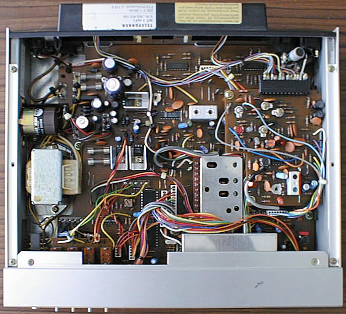
The MT 1 was Telefunken's high-class offering in the line of Midi-sized (30x30 cm basic area) Hifi components. It offers almost everything one would expect from a synthesizer tuner at that time, including numeric frequency input, and some nice addons like the 1 kHz, 0dB test signal generator. It is part of the M 1 component system, and shares the unusual housing concept: the housing is made of an inner frame, and aluminium profiles attached to it make the 'outer skin'. This housing concept is similar to laboratory devices and in contrast to standard housing concepts of Hifi devices at that time, which were based on bended metal sheets. It gives the whole system a very worthy look, and Telefunken won an industry design award for it.
FM/MW/LW, station scan/store, numeric frequency input, test signal generator for record level adjustment, exact tuning indicator, built-in ferrite AM antenna
(taken from the user's manual)
| FM Section | |
|---|---|
| Wave Range: | 87.5 - 108 MHz |
| Circuits: | 11 (4 tunable) |
| Sensitivity: | 0.9 µV at 75 Ohms |
| (26 dB / 40 kHz modulation) | |
| Limiter Threshold: | < 0.8 µV |
| Intermediate Frequency: | 10.7 MHz |
| IF Bandwidth: | 160 kHz |
| Selection: | 75 dB |
| Mirror Selection: | > 70 dB |
| Capture Ratio: | 1.5 dB |
| Pilot Tone Suppression: | > 54 dB |
| Aux Carrier Suppression: | > 60 dB |
| Frequency Range: | 20 Hz - 15 kHz |
| Distortion Factor: | < 0.4 % |
| Channel Separation: | 40 dB |
| Extraneous Voltage Ratio: | > 63 dB |
| S/N Ratio: | > 62 dB |
| Strength Indicator Range: | 2 µV - 5 mV |
| Automatic Stereo Threshold: | 5 µV |
| Calibration Precision: | 0 kHz |
| AM Section | |
| Wave Ranges: | LW 137 - 372 kHz |
| MW 522 - 1611 kHz | |
| Circiuts: | 6(9)(2 tunable) |
| Intermediate Frequency: | 468 kHz |
| IF Bandwidth: | 5.5 kHz |
| Extraneous Voltage Ratio: | 45 dB |
| Calibration Precision: | 0 kHz |
| Strength Indicator Range: | 40 µV - 10 mV |
| General | |
| Semiconductors: | 19 integrated circuits |
| 25 transistors | |
| 84 diodes | |
| 30 LEDs | |
| Mains Supply: | 220/110 V |
| Fuses: | secondary 3 x T 0.4 A, |
| 1 x T 0.05 A | |
| Dimensions: | 298 x 57.5 x 250 mm |
| Weight: | approx. 3.1 kg |
Even when the MT 1 seems to be turned off, it actually isn't. The display and receiver sections are off, but the microprocessor is still supplied from the mains transformer. The power switch operates on the secondary side, which means that it has to switch higher currents than a normal primary-side switch. I had an MT 1 where one of the power switch's contacts was burned...
Since the microprocessor never shuts down (the preprogrammed stations would get lost), it also has to run while the tuner is disconnected from the mains supply. A NiCd accumulator provides this and is recharged while the tuner is connected to mains. However, there is no protection against deep discharge if the tuner is stored for longer time, which can make the accumulator fail and leak. The accumulator's form factor is a bit uncommon, a cylinder screwed to the chassis like a large electrolytic capacitor. Makes replacing a bit difficult, you will have to improvise...
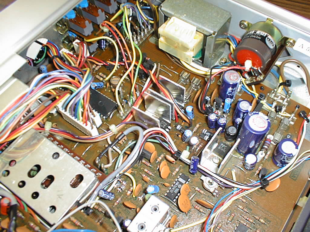
A problem that showed up during production of the MT 1 is the reset circuitry of the microprocessor. It does not properly reset the processor when the accumulator's voltage drops below the lower allowed limit, which means that the processor will crash and might not come up again when the tuner is again connected to mains. Customers came in with inoperable tuners, so Telefunken had to think of a 'quick fix': lucikly, there were free contacts in the Scan and Store buttos, so the two were connected in series and formed a manual reset for the microprocessor. A red flyer was added to the manual that instructed the user to press Scan ans Store simultaneously in such situations. Of course you lost preprogrammed stations, but at least the device was operable again...you might also have to perform this 'reset procedure' after you replaced a failed accumulator.
if you look closely at the detail photo, you can see the pale yellow cable soldered to a resistor that comes from the upper switch board.
(taken from the service manual)
| Cabinet Parts | ||
|---|---|---|
| Position | Order No. | Designation |
| 339 132 019 | front mask, complete | |
| 301 | 339 132 020 | front mask |
| 302 | 339 272 013 | indicator window |
| 303 | 339 337 013 | digital display dial |
| 304 | 339 273 014 | digital display window |
| 305 | 339 270 010 | knob guide for mains switch |
| 306 | 339 272 015 | knob frame for tuning knob |
| 307 | 339 222 028 | tuning knob |
| 308 | 339 220 015 | knob for mains switch |
| 309 | 339 272 014 | knob frame for store board |
| 310 | 339 222 025 | knob for store board |
| 311 | 339 222 026 | knob for input |
| 312 | 339 222 027 | contact knob |
| 313 | 339 270 009 | knob frame, 4-fold |
| 314 | 339 220 017 | push button (small) |
| 315 | 339 915 020 | pressure spring |
| 319 | 339 230 008 | cabinet lid |
| 320 | 339 232 022 | side part |
| 321 | 339 037 010 | rear panel |
| 322 | 339 873 028 | antenna cover |
| 324 | 339 873 035 | bottom plate |
| 325 | 339 060 006 | foot |
| Mechanical Parts | ||
| Position | Order No. | Designation |
| 328 | 339 037 007 | chassis front plate |
| 329 | 339 037 008 | chassis left side |
| 330 | 339 037 009 | chassis right side |
| 332 | 339 872 023 | mounting plate for mains transformer |
| 333 | 339 873 030 | shielding for digital display |
| 334 | 339 873 031 | shielding, upper part, for digital display |
| 335 | 339 873 032 | shielding frame for digital display |
| 336 | 339 873 033 | angle |
| 337 | 339 873 034 | insulating plate |
| 338 | 339 873 029 | mounting angle for digital display |
| 341 | 339 337 008 | FM Board |
| Position | Order No. | Designation |
| C 262 | 339 510 053 | trimmer 5-50 pF |
| C 280 | 309 414 700 | Al-electr. cap. 1000 µF/16 V |
| D 201/202/204/ | 309 327 919 | diode 1 S 446 |
| 214/215 | ||
| D 203 | 339 529 137 | diode 05 Z 6.2 L |
| D 205 | 339 529 253 | diode 05 Z 5.1 L |
| D 206-209/ | 339 529 017 | diode 1 S 1555 |
| 216-220/ | ||
| 304-308/324 | ||
| D 210-213 | 339 529 254 | diode 05 Z 6.8 L |
| D 301/312 | 339 529 092 | diode KB 262 |
| D 302/315-317/ | 339 529 101 | diode SR 1 K |
| 309/311/ | ||
| 319-322 | ||
| D 306 | 339 529 255 | diode 05 Z 8.2 L |
| D 313/314 | 339 529 256 | diode 05 Z 16 L |
| D 318 | 339 529 177 | diode 05 Z 12 U |
| D 323 | 339 520 051 | diode DBA 10 B |
| FI 201/202 | 339 368 016 | ceramic filter |
| FI 203 | 339 368 017 | ceramic filter |
| FI 201/202 | 339 368 014 | low-pass filter |
| FU 201 | 339 572 004 | fuse T 400 mA |
| FU 202 | 339 570 001 | fuse T 50 mA |
| FU 203/204 | 339 570 063 | fuse T 250 mA |
| IC 201 | 339 575 227 | IC TA 7060 AP |
| IC 202 | 339 575 228 | IC HA 12412 |
| IC 203 | 339 368 173 | IC TCA 4500 A |
| IC 204/210 | 339 575 087 | IC NJM 4558 D |
| IC 205 | 339 575 229 | IC MC 14066 |
| IC 206/207 | 339 575 067 | IC TC 4001 BP |
| IC 208/209 | 339 575 230 | IC TA 75902 |
| IC 211 | 339 575 232 | IC TC 9125 P |
| IC 212 | 339 575 231 | IC TD 6102 P |
| IC 213 | 339 575 233 | IC TC 9129 P |
| IC 214/215 | 339 575 234 | IC MC 7805 CT |
| IC 216 | 339 575 235 | IC MC 7812 CT |
| L 201 | 339 347 040 | choke coil |
| L 202 | 339 347 039 | detector coil |
| L 203 | 339 368 652 | IF filter |
| L 204 | 339 347 037 | oscillator coil |
| L 205 | 339 347 038 | choke coil |
| R 220 | 339 502 015 | variable resistor 5 kOhm |
| R 223 | 339 508 651 | variable resistor 10 kOhm |
| R 257 | 339 502 016 | variable resistor 220 kOhm |
| R 339 | 339 508 653 | variable resistor 20 kOhm |
| S 201 | 339 442 017 | contact silder |
| QU 201 | 339 344 012 | crystal 9 MHz HC-18/U |
| T 201/208 | 339 556 386 | transistor 2 SC 380 A |
| T 202 | 339 556 299 | transistor 2 SC 1815 GR |
| T 203/209/211/ | 339 556 379 | transistor 2 SC 1815 |
| 214/215 | ||
| T 204-207 | 339 556 380 | transistor 2 SA 965 |
| T 210 | 339 556 378 | transistor 2 SC 1015 |
| T 212/213 | 339 556 306 | transistor 2 SC 2655 |
| 342 | 339 337 010 | AM Board |
| Position | Order No. | Designation |
| C 402/413 | 339 510 054 | foil trimmer 3-13 pF |
| C 405/416 | 339 510 055 | foil trimmer 6-35 pF |
| D 405 | 339 529 264 | diode KV 1225 Y |
| D 402/409/410 | 339 529 262 | diode MC 301 |
| D 403/404/406/ | 339 529 263 | diode MC 302 |
| 408/411/412 | ||
| D 407 | 339 529 261 | LED SLP 133 B |
| D 413/414 | 339 327 920 | LED 1 S 446 D |
| IC 401 | 339 575 236 | IC TCA 440 N |
| L 401 | 339 347 038 | choke coil |
| L 402 | 339 347 044 | choke coil |
| L 403 | 339 347 042 | oscillator coil MW |
| L 404 | 339 347 043 | oscillator coil LW |
| L 405 | 339 368 015 | IF filter |
| L 406/407 | 339 368 653 | IF filter |
| R 430 | 339 502 022 | variable resistor 2 kOhm |
| T 401 | 339 556 381 | transistor 2 SC 380 OY |
| 344 | 339 337 011 | Digital Display Board |
| Position | Order No. | Designation |
| 343 | 339 337 009 | FM mixing unit |
| D 601-604/ | 339 529 259 | LED LN 224 RP red |
| 606-611 | ||
| D 605 | 339 529 260 | LED N 324 GP green |
| LED 601 | 339 529 258 | LED TLG 352 |
| LED 602/603 | 339 529 257 | LED TLG 354 |
| IC 601 | 339 575 237 | IC TC 4511 BP |
| IC 602 | 339 575 243 | IC TD 62301 |
| 3 | 339 337 013 | digital display dial |
| 4 | 339 237 014 | digital display window |
| 345 | 339 337 014 | Main Tuning Board |
| Position | Order No. | Designation |
| D 701-704 | 339 529 017 | diode 1 S 1555 |
| S 701/702 | 339 442 020 | touch contact |
| 346 | 339 337 015 | Store Board |
| Position | Order No. | Designation |
| D 501-506/517/ | 339 529 251 | LED LN 221 RP red |
| 518 | ||
| D 519-521 | 339 529 017 | diode 1 S 1555 |
| S 501 | 339 442 020 | touch contact |
| S 502-511 | 339 442 018 | touch contact |
| T 501-504 | 339 556 379 | transistor 2 SC 1815 Y GR |
| 347 | 339 337 016 | Type of Operation Board |
| Position | Order No. | Designation |
| D 801 | 339 529 017 | diode 1 S 1555 |
| S 801 | 339 442 017 | push button assembly, 4-fold |
| BU 901 | 339 542 041 | antenna socket FM |
| BU 902 | 339 542 042 | antenna socket AM/FM |
| BU 903 | 339 542 043 | output socket, 5 contacts |
| BU 904 | 339 542 044 | mains socket |
| L 701 | 339 347 048 | antenna coil |
| L 902 | 339 348 655 | choke coil 2.2 µH |
| L 903 | 339 347 045 | adjustment coil 3.3 µH |
| L 904 | 339 452 012 | ferrite antenna |
| S 901 | 339 442 019 | mains switch |
| TR 901 | 339 312 009 | mains transformer |
| 350 | 339 457 010 | support for antenna |
| 352 | 339 168 006 | battery holder with battery |