

Analog Tuner
1981
DEM 215,-
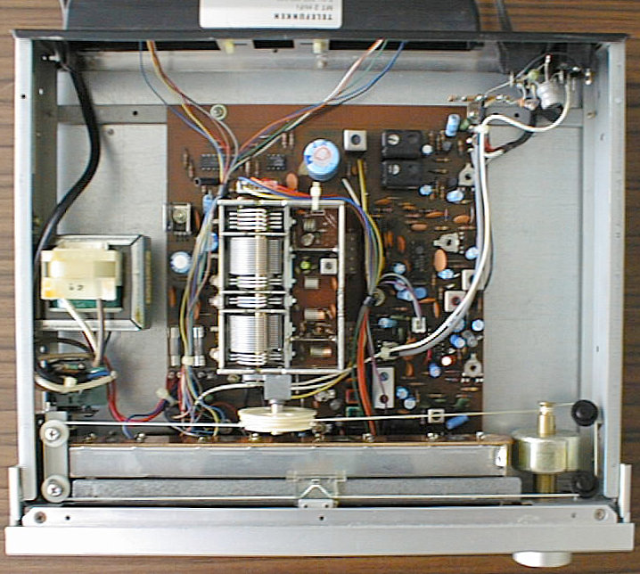
The MT 2 was part of Telefunken's M 2 Midi-sized, low cost component system. The M 2 was by far the cheapest component system Telefunken sold at that time. Its principle was to offer a good price-to-performance ratio, by leaving out non-essential 'luxury' features. Consequently, the MT 2 is just a 'simple' analog tuner, but with a beautiful backlighted dial that is larger than e.g. the dial of the much larger RT 100, plus a dual-gate MOS frontend section that was state-of-the-art at that time.
FM/MW/LW, built-in ferrite AM antenna
(taken from the service manual)
| FM Section | |
|---|---|
| Wave Ranges: | FM = 87.5 - 108 MHz |
| MW = 520 - 1610 kHz | |
| LW = 140 - 360 kHz | |
| Circuits: | AM 6 / FM 13 |
| Intermediate Frequency: | AM 460 kHz / FM 10.7 MHz |
| IF Bandwidth: | AM 5 kHz / FM 150 kHz |
| Sensitivity: | FM 0.9 µV Mono |
| (SNR 26 dB, 1000Hz, | |
| 40 kHz modulation, 75 Ohms) | |
| Distortion Factor FM: | < 0.5 % Mono / < 0.8 % Stereo |
| (1 kHz, 40 kHz modulation | |
| S/N Ratio: | > 63 dB Mono / > 60 % Stereo (eff.) |
| Pilot Tone Suppression: | > 54 dB (acc. to DIN 45 500) |
| Channel Separation: | > 36 dB / 1 kHz |
| General | |
| Semiconductors: | 7 integrated circuits |
| 7 transistors | |
| 6 LEDs | |
| 12 diodes | |
| 1 mains rectifier | |
| Mains Supply: | 220 V 50/60 Hz |
| Fuses: | secondary T 200 mA, T 800 mA |
| Dimensions: | 298 x 64 x 280 mm |
| with ferrite antenna | |

None known, except for the usual burned-out light bulbs. The MT 2 uses four fuse-shaped bulbs that are located entirely inside the closed light box. This gives the MT 2's dial its good appearance, however it is necessary to remove the front cover and scale mask to get access to the bulbs.
(taken from the service manual)
| Cabinet Parts | ||
|---|---|---|
| Position | Order No. | Designation |
| 301 | 339 132 125 | front panel |
| 302 | 339 272 107 | dial window |
| 303 | 339 272 106 | frame for field strength control |
| 305 | 339 222 107 | tuning knob |
| 306 | 339 210 106 | push button |
| 307 | 339 222 108 | knob frame |
| 308 | 339 227 106 | dial |
| 309 | 339 227 107 | dial pointer |
| 310 | 339 230 115 | push button guide |
| 312 | 339 132 107 | cabinet cover |
| 313 | 339 232 106 | side part (plastic) |
| 314 | 339 132 108 | bottom plate |
| 315 | 339 060 106 | foot |
| 317 | 339 227 109 | antenna cover |
| 320 | 339 132 110 | front mounting plate |
| 321 | 339 232 113 | side part, left hand |
| 322 | 339 232 144 | side part, right hand |
| 324 | 339 135 108 | rear panel |
| 326 | 339 566 106 | lamp housing |
| 328 | 339 227 110 | angle sheet for dial frame, left |
| 329 | 339 227 111 | angle sheet for dial frame, right |
| 330 | 339 227 112 | angle sheet for dial frame, down |
| 331 | 339 902 106 | dial cord spring |
| 332 | 339 737 108 | dial roller |
| 333 | 339 902 107 | spring |
| 334 | 339 227 108 | pointer holder |
| 335 | 339 737 106 | tuning shaft |
| 336 | 339 457 107 | antenna holder |
| 338 | 339 870 107 | mains switch rod |
| 340 | 339 232 109 | RF-IF-AF-Board, cpl. |
| Position | Order No. | Designation |
| C 254 | 309 414 684 | Al-electr. cap 2200 µF / 25 V |
| C 234/238 | 339 510 054 | trimmer capacitor 3-13 pF |
| C 237/239 | 339 510 055 | trimmer capacitor 6-35 pF |
| D 201/202/208/ | 309 327 919 | diode 1 S 446 |
| 209 | ||
| D 203-207 | 339 529 017 | diode 1 S 1555 |
| D 210-212 | 339 529 248 | diode SR 1 K |
| D 213 | 339 520 051 | diode DBA 10 B |
| D 214 | 339 529 177 | diode 0 5 Z 12 U |
| FU 201 | 309 627 901 | fuse T 315 mA |
| FU 202 | 309 627 918 | fuse T 800 mA |
| IC 201 | 339 575 227 | IC TA 7060 AP |
| IC 202 | 339 575 253 | IC LA 1231 N |
| IC 203 | 339 575 254 | IC AN 115 |
| IC 204 | 339 575 236 | IC TCA 440 N |
| IC 205 | 339 575 252 | IC NJM 4558 |
| IC 206 | 339 575 230 | IC TA 75 902 |
| FL 201/202 | 339 368 014 | low-pass filter |
| CL 201/202 | 339 368 107 | ceramic filter |
| L 203 | 339 368 015 | filter |
| L 206 | 339 347 107 | oscillator coil |
| L 207 | 339 347 106 | oscillator coil |
| L 208 | 339 368 652 | filter |
| L 213 | 339 368 106 | filter |
| L 202 | 339 347 108 | choke coil |
| R 215 | 339 508 654 | variable resistor 50 KOhm |
| R 230/272 | 339 508 651 | variable resistor 10 KOhm |
| R 244 | 339 502 022 | variable resistor 2 KOhm |
| S 201 | 339 442 106 | push button assembly |
| T 201 | 339 556 386 | transistor 2 SC 380 |
| T 202/203/205/ | 339 556 292 | transistor 2 SC 1815 Y |
| 206 | ||
| T 204 | 339 556 185 | transistor 2 SC 1382 |
| 341 | 339 337 109 | mixing unit with variable capacitor |
| 342 | 339 337 106 | Field Strength Control, cpl. |
| Position | Order No. | Designation |
| D 301-306 | 339 529 281 | LED, red |
| D 307 | 339 529 280 | LED, green |
| 343 | 339 337 107 | Mains Switch, cpl. |
| Position | Order No. | Designation |
| S 001 | 339 440 108 | mains switch |
| C 001 | 339 590 098 | anti-interference capacitor |
| 344 | 339 566 068 | lamp holder, cpl. |
| BU 801 | 339 542 041 | antenna socket AM |
| BU 802 | 339 542 042 | antenna socket FM |
| L 801 | 339 348 655 | choke coil |
| L 802 | 339 347 109 | ferrite antenna |
| L 803 | 339 347 045 | coil 3.3 mH |
| L 804 | 339 347 048 | symmetry transformer |
| LA 801-804 | 339 560 048 | dial bulb 170 mA / 6.3 V |
| TR 801 | 339 312 107 | mains transformer |
| 345 | 339 480 006 | power cord |
| 346 | 339 488 106 | AF cable |
| 339 452 107 | AM antenna | |
| 339 452 106 | FM antenna |