

Cassette Deck
1981
The RC 100 is the simplest deck of the Silver Series. Designed as a low-end device, it lacks a couple of the functions present in the better ones. The most notable is the mechanical drive control, in contrast to the electronic control of the better ones. Telefunken euphemistically called this a "Soft Touch Mechanism". This term means that your fingers don't have to provide the full power to move all levers and wheels into the needed positions. Instead, the buttons influence a sort of 'mechanic state machine' that is driven by the motor, i.e. the motor has to do the work of lifting the head carrier up towards the cassette.
Further missing features are the support for FeCr tapes (not that important...), the memory function of the tape counter (I'm really missing that sometimes) and the timer functions (really not to replace in some situations!). But well, it's an entry-level deck.
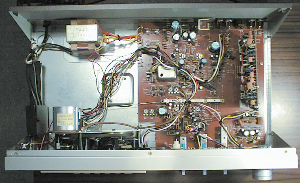
The look at the innards clearly demonstrates that a case of thi size is absolutely unnecessary. The mechanics define the height, and width and depth are dictated by the size of the other components in the stack.
"Soft-Touch-Mechanism", HighCOM, Dolby-B compatible, supports Fe/Cr/Metal tapes, switchable multiplex filter, 2 peak-level displays, mechanical tape counter
Radio/Phono/Tape (DIN); Microphone/Aux (DIN); Line in/out (4xCinch); Headphone (6.3mm)
(taken from the service manual)
| Tape Speed: | 4.75 cm/s ±1.5% |
| Frequency Range: | 30-12500 Hz (Fe2O3) |
| 30-15000 Hz (CrO2) | |
| 30-15000 Hz (Metal) | |
| Tone Height Variations: | <= ±0.2 % (Record + Play) |
| <= ±0.16 % (Play only) | |
| Distortion Factor: | <= 1 % (Fe2O3) |
| <= 3 % (CrO2) | |
| <= 2 % (Metal) | |
| S/N Ratio with High COM NR: | >= 68 dB (Fe2O3) |
| >= 70 dB (CrO2) | |
| >= 69 dB (Metal) | |
| Erase Dampening: | >= 70 dB |
| Erase Frequency: | 85 kHz ±1 kHz |
| Reduction of Max. High Frequency | |
| Level at 10 kHz: | <= 14 dB (Fe2O3) |
| <= 12 dB (CrO2) | |
| <= 5 dB (Metal) | |
| Channel Separation (1 kHz) | >= 30 dB (Stereo) |
| Input Sensitivities/Impedances: | Radio/Micro: 0.4 mV / 6 kOhm |
| Aux: 45 mV / 680 kOhm | |
| Line: 180 mV / 60 kOhm | |
| Output Voltages/Impadances: | Radio 1.0 V / 4 kOhm |
| Headphone > 0.2 V / 400 Ohm | |
| Playback Deemphasis: | 3180 µs / 120 µs (Fe2O3) |
| 3180 µs / 70 µs (CrO2) | |
| 3180 µs / 70 µs (Metal) | |
| Semiconductors: | 9 integrated circuits |
| 28 transistors | |
| 3 diodes | |
| 2 zener diodes | |
| 8 rectifiers | |
| 24 LEDs | |
| Mains Supply: | 220/110 V |
| Mains Frequency: | 50/60 Hz |
| Dimensions: | 435x111x250 mm |
| Weight: | 4.5 kg |
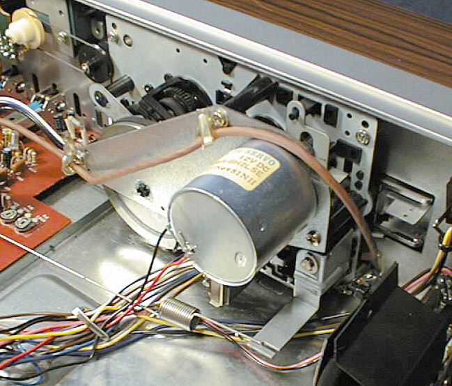
Like all cassette mechanisms with only one motor, the arrangement of wheels, gears and belts is relatively complex to transfer the motor's rotations to three different drives. For fast forward and rewind, the transfer to the reels is done via rubber wheels and friction. The rubber however wears out over the years, becomes hard or breaks up, and the friction drive doesn't work anymore. Typically, record and play still work since that drive is based on gears. I have no patent solution for this, but I see no other option than replacing the rubber parts. Original parts are not available any more, so your creativity is challenged...
Similar to the RC 200, the two small belts driving the tape counter from the right reel also loose their properties over the years. Such belts however are standard components and should be easy to replace if the diameter (approx. 45 mm) fits.
(taken from Telefunken's 1981-1991 Service Handbook, and the service manual)
| Cassette Drive | ||
|---|---|---|
| Position | Order No. | Designation |
| HSK | 339 350 110 | record/playback head |
| LK | 339 355 006 | erase head |
| M 1 | 339 300 008 | motor |
| S 305 | 339 440 853 | micro switch |
| 4 | 339 337 152 | LED display for drive |
| 5 | 339 725 110 | head bearing |
| 6 | 339 720 106 | head support plate |
| 8 | 339 705 117 | release lever |
| 9 | 339 905 107 | pressure spring f. rec/play head |
| 10 | 339 900 108 | rotating spring |
| 11 | 339 755 109 | capstan roll, complete |
| 339 755 652 | capstan roll, universal | |
| 12 | 339 910 114 | pressure spring |
| 13 | 339 715 851 | calotte bearing |
| 15 | 339 755 107 | roll arm |
| 16 | 339 755 108 | gear |
| 17 | 339 905 108 | pull spring |
| 18 | 339 810 111 | gearbox arm |
| 19 | 339 735 007 | gear |
| 21 | 339 705 108 | stop-start arm |
| 22 | 339 705 109 | operating arm |
| 23 | 339 705 115 | lock arm |
| 24 | 339 705 116 | lock plate |
| 26 | 339 745 106 | brake arm |
| 27 | 339 745 107 | pressure spring for brake arm |
| 28 | 339 740 111 | decreasing reel's plate, complete |
| 29 | 339 915 107 | pull spring |
| 30 | 339 905 109 | pull spring |
| 31 | 339 905 110 | rotating spring |
| 32 | 339 905 111 | pull spring |
| 33 | 339 705 110 | pre-run lever |
| 35 | 339 760 107 | intermediate wheel lever, cpl. |
| 36 | 339 760 108 | intermediate wheel cpl. |
| 37 | 339 915 119 | spring |
| 38 | 339 705 111 | pre-run arm |
| 39 | 339 915 871 | mass pressure spring |
| 41 | 339 915 112 | pull spring |
| 42 | 339 825 110 | gear A |
| 43 | 339 825 111 | gear B |
| 44 | 339 825 112 | cam lever |
| 45 | 339 810 113 | cam stop A |
| 46 | 339 810 110 | cam stop B |
| 47 | 339 915 113 | rotating spring |
| 48 | 339 735 110 | motor roll |
| 51 | 339 210 122 | push button assembly, complete |
| 52 | 339 710 108 | flywheel |
| 53 | 339 730 109 | driving belt |
| 55 | 339 910 115 | holding spring for cassette |
| 56 | 339 740 112 | increasing reel's plate, complete |
| 57 | 339 900 107 | rotating spring |
| 58 | 339 810 106 | holder, left |
| 59 | 339 810 107 | holder, right |
| 60 | 339 810 108 | bearing angle, right |
| 61 | 339 810 109 | bearing angle, left |
| 62 | 339 915 108 | rotating spring, right |
| 63 | 339 915 109 | rotating spring,left |
| 64 | 339 705 113 | record lever C |
| 65 | 339 705 114 | record lever D |
| 66 | 339 915 110 | pull spring |
| 67 | 339 870 118 | coupling |
| 68 | 339 905 112 | pressure spring |
| 69 | 339 710 107 | flywheel bearing |
| 70 | 339 705 112 | record lever B |
| 71 | 339 915 120 | pull spring |
| 339 740 404 | reel plate right | |
| 72 | 339 337 152(a) | LED display for drive control |
| Cassette Drive | ||
| Position | Order No. | Designation |
| 339 420 106 | sockets plate | |
| 339 540 149 | DIN socket, 8 contacts | |
| 309 411 660 | Al-electr. cap. 10 µF / 100V | |
| D 1-3/5 | 339 529 320 | LED SG 321 D |
| D 4 | 339 529 323 | LED SR 531 D |
| D 501-508 | 339 529 188 | diode S 5277 B |
| D 509 | 339 529 187 | diode RD 24 EB 3 |
| D 510 | 339 529 017 | diode 1 S 1555 |
| FU 501 | 339 572 004 | fuse T 400 mA |
| FU 502 | 339 572 005 | fuse T 500 mA |
| IC 1-3 | 339 575 319 | IC TA 75558 S |
| L 581 | 339 345 112 | oscillator coil |
| R 381/383/581/ | 339 505 006 | adjustable resistor 20 kOhm |
| 1381/1383 | ||
| R 382/1382 | 339 505 107 | adjustable resistor 20 kOhm |
| R 384/1384 | 339 505 108 | adjustable resistor 100 kOhm |
| R 385/1385 | 339 505 110 | adjustable resistor 10 kOhm |
| R 583 | 339 505 007 | adjustable resistor 5 kOhm |
| S 301 | 339 440 014 | switch, 12-fold |
| S 302 | 339 440 120 | switch (tape selector) |
| S 303 | 339 440 119 | switch (High Com) |
| S 304 | 339 440 118 | switch (MPX-micro) |
| T 301/302/307/ | 339 556 474 | transistor 2 SC 2240 |
| 308/1301/1307/ | ||
| 1308 | ||
| T 303-306/309/ | 339 556 120 | transistor 2 SC 828 |
| 310/582/ | ||
| 1303-1306/ | ||
| 1309/1310 | ||
| T 501 | 339 556 481 | transistor 2 SD 880 |
| T 502/581 | 339 556 479 | transistor 2 SC 2209 |
| T 503/504 | 339 556 482 | transistor 2 SA 1015 |
| T 583/584 | 339 556 212 | transistor 2 SC 1815 |
| T 505 | 339 556 480 | transistor 2 SC 2655 |
| LED Display | ||
| Position | Order No. | Designation |
| 76 | 339 337 151 | LED display, complete |
| D 901-907/ | 339 529 350 | LED GL 9 NG 4 |
| 1901-1907 | ||
| D 908-910/ | 339 529 348 | LED GL 9 PR 4 |
| 1908-1910 | ||
| IC 901 | 339 575 317 | IC TA 7666 P |
| IC 902 | 339 575 318 | IC TA 7667 P |
| High Com Module | ||
| Position | Order No. | Designation |
| 77 | 339 355 031 | High Com module |
| FI 701/1701 | 339 365 119 | filter 84.5 kHz |
| FI 702/1702 | 339 365 107 | filter MPX 19 kHz |
| IC 702/1702 | 339 575 081 | IC HD 14066 BP |
| T 801 | 339 556 480 | transistor 2 SC 2655 |
| T 700/1700 | 339 505 111 | adjustable resistor |
| 78 | 339 540 076 | headphone socket |
| S 1 | 339 440 850 | mains switch |
| TR 1 | 339 310 110 | mains transformer |
| 339 480 150 | power cord | |
| Cabinet Parts | ||
| Position | Order No. | Designation |
| 80 | 339 120 107 | front mask |
| 81 | 339 130 110 | side mask for front mask |
| 82 | 339 220 110 | mains switch guiding |
| 83 | 339 220 111 | counter reset button guiding |
| 84 | 339 125 106 | cassette frame |
| 85 | 339 160 107 | cover mask for drive |
| 86 | 339 220 108 | record level button, upper part |
| 87 | 339 220 109 | record level button, lower part |
| 88 | 339 205 106 | switch knob |
| 89 | 339 220 106 | mains switch knob |
| 90 | 339 210 120 | knob (large) |
| 91 | 339 210 119 | knob (small) |
| 92 | 339 220 107 | key for eject flap |
| 93 | 339 210 121 | counter reset knob |
| 94 | 339 270 114 | counter window |
| 96 | 339 230 108 | decorating ring, 30 mm |
| 97 | 339 230 107 | decorating ring for micro socket |
| 99 | 339 150 109 | cabinet upper part |
| 100 | 339 135 109 | chassis, rear part |
| 101 | 339 060 108 | foot |
| 102 | 339 155 107 | ground plate |
| 105 | 339 760 109 | roll for counter |
| 106 | 339 730 110 | belt for counter |
| 107 | 339 780 108 | counter |
| 108 | 339 879 122 | distance holder |
| 109 | 339 915 117 | pull spring |
| 110 | 339 825 115 | mains switch shaft |
| 111 | 339 440 122 | switch holding angle |
| 112 | 339 825 113 | lever |
| 113 | 339 270 115 | LED ground plate |
| Documentation | ||
| Position | Order No. | Designation |
| 319 441 611 | service information |