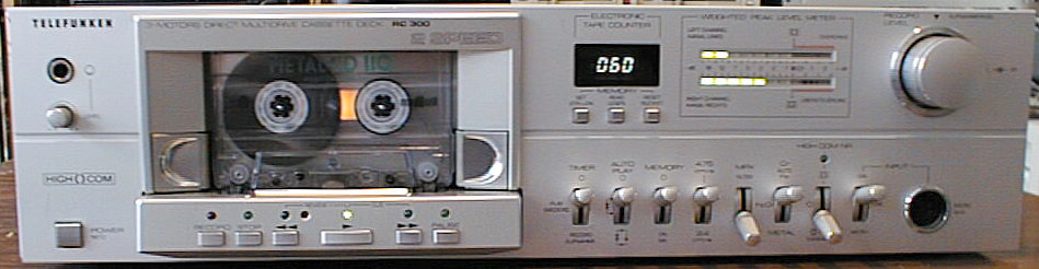

Cassette Deck
1981
The RC 300 is arguably one of the best, luxurious...and most expensive tape decks Telefunken has ever built. No tape deck before or after had a longplay option, or a three-motor mechanics. The drive mechanism is the MultiDrive mechanism that was developed by Papst, a company that is today still known for the quality of their fans. With a separate motor for the capstan and each reel, there is no need for belts or rubber rolls, all controls are done electronically and there are much fewer parts that can fail.
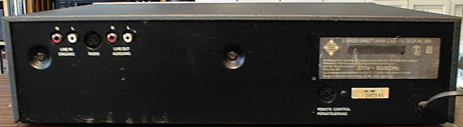
The RC 300 was part of Telefunken's T 300 high-end component system, and it has a remote control input that allows the drive functions to be controlled via the RP 300 pre-amplifier.

Similar to other T 300 components, the RC 300 was manufactured in Germany and its inner construction is significantly different to the RC 100 or RC 200 decks, which were manufactured in fareast. One might think that it was designed by an engineer who previously designed TV chassis - metal-framed PCBs that could be swung out for servicing were typical for TVs built in the 60s/70s.
three-motor drive, two tape speeds, auto rewind/auto play, electronic tape counter with memory function, switchable MPX filter, remote control input.
(taken from the user's manual)
| Tape Speed 4.75 cm/s +/- 1.0 % | |
|---|---|
| Tone Height Variations: | <= +/- 0.1 % (Rec + Play) |
| <= +/- 0.08 % (only Play) | |
| Frequency Range: | Fe2O3: 30-16000 Hz |
| CrO2: 30-18000 Hz | |
| FeCr: 30-16000 Hz | |
| Metal: 30-18000 Hz | |
| Distortion Factor: | Fe2O3 and FeCr: <= 1 % |
| CrO2: <= 3 % | |
| Metal: <= 2 % | |
| Reduction of Max. High Frequency | |
| Level at 10 kHz: | Fe2O3: <= 12 dB |
| CrO2: <= 10 dB | |
| FeCr: <= 10 dB | |
| Metal: <= 2 dB | |
| S/N Ratio with High COM NR: | Fe2O3: 74 dB |
| CrO2: 78 dB | |
| FeCr: 75 dB | |
| Metal: 77 dB | |
| Play Deemphasis: | Fe2O3: 3180 µs/120 µs |
| CrO2: 3180 µs/70 µs | |
| FeCr: 3180 µs/120 µs | |
| Metal: 3180 µs/70 µs | |
| Tape Speed 2.4 cm/s +/- 1.5 % | |
| Tone Height Variations: | <= +/- 0.2 % (Rec + Play) |
| <= +/- 0.15 % (only Play) | |
| Frequency Range, Metal: | 30-12500 Hz |
| Distortion Factor, Metal: | <= 2 % |
| Reduction of Max. High Frequency | |
| Level at 10 kHz, Metal: | <= 10 dB |
| S/N Ratio with High COM NR, Metal: | 72 dB |
| Play Deemphasis, Metal: | 3180 µs/120 µs |
All data about distortion, reduction of max. high frequency level at 10 kHz, and S/N ratio are based on a tape magnetization level of 200 nWb/m.

Due to its three-motor drive, the RC 300 is relatively insensitive to the mechanical failures typically known from other cassette decks. There is another small problem: the level indicators are integrated devices, i.e. the driver chip is integrated into the display. Such devices are not made these days any more, and they are said to be somewhat...unreliable. I've had one deck with broken indicators so far, and I had to think of a 'replacement circuit' with two UAA 180 driver circuits. I've heard reports of other people who used the LED indicators from an RC 200, or people who replaced the indicators with something completely different - which is basically justified: 10 LEDs per channel, just as many as for the simpler decks, is not too much for such a high-class deck...
(taken from the service manual)
| Cabinet Parts | ||
|---|---|---|
| Position | Order No. | Designation |
| 1 | 339 130 109 | front mask, complete |
| 2 | 339 130 107 | side panel, right hand |
| 3 | 339 130 108 | side panel, left hand |
| 4 | 339 160 106 | cassette frame, printed |
| 5 | 339 270 109 | counter window |
| 6 | 339 270 110 | ring for microphone jack |
| 7 | 339 270 111 | insert for recording level |
| 10 | 339 201 107 | var. knob 1 for recording level |
| 11 | 339 201 108 | var. knob 2 for recording level |
| 12 | 339 210 109 | memory button |
| 13 | 339 210 110 | tumbler switch button |
| 14 | 339 201 109 | var. button for headphone level |
| 15 | 339 210 111 | mains button with switch rod |
| 16 | 339 210 112 | microswitch for cassette flap |
| 17 | 339 210 113 | button cover for logic circuit |
| 18 | 339 210 114 | button for logic circuit |
| 19 | 339 210 115 | button for logic circuit |
| 20 | 339 170 107 | mask for cassette mechanism |
| 25 | 339 150 106 | housing, upper part |
| 26 | 339 060 107 | foot |
| 27 | 339 905 966 | spring for foot |
| 28 | 339 064 109 | felt washer |
| Mechanical Parts | ||
| Position | Order No. | Designation |
| 29 | 339 820 106 | bearing support |
| 30 | 339 870 111 | clamping piece for PCB |
| 31 | 339 870 112 | clamping piece for switch board |
| 32 | 339 870 113 | supporting angle |
| 33 | 339 870 114 | supporting angle |
| 36 | 339 785 106 | counter support |
| 37 | 339 870 110 | support for level indicator |
| 38 | 339 910 107 | bow spring |
| 39 | 339 910 106 | flat spring for mask |
| 40 | 339 870 115 | supporting angle |
| 41 | 309 900 333(a) | support for mains switch |
| 42 | 339 870 116 | cable socket for pull-relief |
| 43 | 339 870 117 | module holder |
| 44 | 339 870 961 | LED holder, 2-fold |
| 45 | 339 870 108 | LED holder, 3-fold |
| 46 | 309 870 109 | LED holder, 3-fold |
| Electrical Parts | ||
| Position | Order No. | Designation |
| BU 801 | 339 540 137 | DIN socket, 5 contacts |
| BU 802 | 309 671 967 | headphone jack, 3 contacts |
| BU 803/804 | 339 540 136 | DIN socket, 8 contacts |
| HSK 1 | 339 350 106 | record/playback head |
| LK 1 | 339 355 950 | erasing head |
| S 1 | 309 630 035 | mains switch |
| FU 1 | 309 627 912 | fuse T 160 mA |
| TR 1 | 339 310 107 | mains transformer |
| ZA 1 | 339 780 107 | electronic counter |
| S 5/6 | 339 440 116 | contact spring set for cassette flap |
| LT 1 | 309 695 928 | mains cable |
| Amplifier Board | ||
| Position | Order No. | Designation |
| C 346/1346 | 339 510 021 | trimmer 8 P 60 P |
| D 505 | 309 325 118 | diode BZX 55 B 2 V 7 |
| D 501-504/506/ | 339 529 034 | diode 1 N 4148 G |
| 507/701-739/ | ||
| 744/752/757/ | ||
| 760-765/801/ | ||
| 802/804-806/ | ||
| 808-822 | ||
| D 740/741 | 309 325 090 | diode BZX 55 C 3 V 3 |
| D 742/743 | 309 325 077 | diode BZX 55 C 10 |
| D 751 | 309 325 951 | diode 1 N 4001 |
| D 803 | 309 325 073 | diode BZX 55 B 8 V 2 |
| D 807 | 309 325 103 | diode BZX 55 C 12 |
| D 745 | 309 327 053 | LED CQY 85 red |
| D 746-750/829 | 309 529 149 | LED CQY 86 green |
| D 823 | 309 325 092 | diode BZX 55 C 9 V 1 |
| ABS 302/1302 | 339 335 106 | level indicator, 10-fold |
| FI 301/1301 | 339 365 006 | MPX filter |
| FI 302/1302 | 339 365 106 | POL filter |
| FU 501 | 309 627 919 | fuse T 1 A |
| FU 502/503 | 309 627 918 | fuse T 800 mA |
| GR 501 | 309 322 902 | rectifier B 80 B 800 |
| GR 502 | 339 520 046 | rectifier B 80 B 800 B 2 |
| IC 301/1301 | 309 368 212 | IC HA 1457 |
| IC 501/503/ | 309 368 295 | IC CD 4016 AE |
| 803/804 | ||
| IC 502/801/ | 339 575 120 | IC UPC 4558 C |
| 806 | ||
| IC 507 | 309 368 105 | IC UA 7818 C |
| IC 504 | 339 575 126 | IC UA 7918 |
| IC 505 | 339 575 068 | IC UA 7824 UC |
| IC 506 | 339 575 069 | IC UA 7815 |
| IC 701/702 | 339 575 259 | IC LM 392 N |
| IC 703 | 309 368 229 | IC MC 14011 CP |
| IC 704 | 309 368 149 | IC MC 14025 CP |
| IC 705 | 339 575 225 | IC TL 9121 P |
| IC 802 | 339 575 260 | IC U 353 M |
| IC 805 | 339 335 855 | IC MC 1458 CP 1 |
| L 301/1301 | 339 345 109 | deemphasis coil |
| L 701-703 | 339 345 350 | anti-interference coil |
| L 801 | 339 345 950 | oscillator coil 85 kHz |
| R 346/1346 | 309 509 705 | var. resistor 50 kOhm |
| R 361/714/ | 309 509 401 | var. resistor 10 kOhm |
| 1361/1714 | ||
| R 384/1384 | 309 509 735 | var. resistor 25 kOhm |
| R 832-834 | 309 504 921 | var. resistor 5 kOhm |
| R 1309 | 339 500 106 | potentiometer 2x20 kOhm |
| R 1357 | 339 500 107 | potentiometer 2x5 kOhm |
| RS 801/802 | 339 405 106 | reed relay |
| S 701-706 | 339 440 964 | touch switch |
| S 801 | 339 440 110 | tumbler switch without button |
| S 802/803/807/ | 339 440 112 | tumbler switch without button |
| 808 | ||
| S 804-806 | 339 440 111 | tumbler switch without button |
| T 301/312/ | 309 001 211 | transistor BC 550 B |
| 1301/1312 | ||
| T 302/313/ | 309 001 242 | transistor BC 550 C |
| 1302/1313 | ||
| T 304-309/311/ | 339 556 224 | transistor BC 548 C |
| 314-318/390/ | ||
| 501-503/506/ | ||
| 717-721/802-805/ | ||
| 809-812/901/ | ||
| 1304-1309/ | ||
| 1311/1314-1318/ | ||
| 1390 | ||
| T 310/701/714/ | 339 556 077 | transistor BC 548 B |
| 715/723/814/ | ||
| 1310 | ||
| T 702/705/706/ | 309 001 226 | transistor BC 558 B |
| 724/808/813 | ||
| T 707/711/712 | 339 556 417 | transistor BC 516 |
| T 709 | 339 556 124 | transistor BC 517 |
| T 713/716 | 339 556 094 | transistor BC 337 |
| T 725 | 339 556 419 | transistor BC 558 C |
| T 726 | 339 001 292 | transistor BC 558 C |
| High COM Module | ||
| Position | Order No. | Designation |
| ABS 301/1301 | 349 355 029 | High COM module |
| C 1 | 309 411 703 | Al.-electr. cap. 22 µF/6.3 V |
| C 2 | 309 410 634 | Al.-electr. cap. 4.7 µF/35 V |
| C 8/12/18 | 309 412 667 | Al.-electr. cap. 47 µF/50 V |
| C 15 | 309 410 655 | Al.-electr. cap. 2.2 µF/25 V |
| C 17/20 | 309 411 647 | Al.-electr. cap. 10 µF/16 V |
| C 22 | 309 413 486 | Al.-electr. cap. 100 µF/10 V |
| IC 2 | 339 575 020 | IC MC 14066 BCP |
| Mechanism | ||
| Position | Order No. | Designation |
| 1 | 339 035 107 | mechanism complete |
| HSK 1 | 339 350 106 | record/playback head |
| LK 1 | 339 355 950 | erasing head |
| 3 | 339 560 107 | lamp |
| 4 | 339 405 109 | set of contacts |
| 5 | 339 405 108 | set of contacts |
| 6 | 339 566 111 | lamp socket |
| 8 | 339 720 108 | head support |
| 9 | 339 910 118 | flat spring |
| 10 | 339 720 107 | plate |
| 11 | 339 900 117 | tension spring |
| 13 | 339 725 107 | pinch roller lever |
| 14 | 339 755 110 | pinch roller |
| 15 | 339 905 113 | pressure spring |
| 16 | 339 905 114 | pressure spring |
| 18 | 339 725 108 | pin |
| 19 | 339 910 117 | pressure spring |
| 20 | 339 725 109 | stopper |
| 22 | 339 740 114 | reel |
| 23 | 339 725 106 | spring ring |
| 24 | 339 905 115 | pressure spring |
| 25 | 339 740 113 | driver |
| 27 | 339 910 116 | torsion spring |
| 29 | 339 915 118 | spring |
| 30 | 339 334 138(a) | PCB for IC TL 170 C |