

Power Amplifier
1981
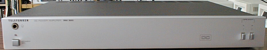
The RM 300 is the power amp of Telefunken's 1981 high-end component system T 300 and as such a natural companion to the RP 300 pre-amplifier. Strangely, it is significantly rarer then the RP 300, though one might were think that they were all bought in pairs. It seems however that a couple of customers only bought the pre-amplifier, and chose a different power amplifier or active speakers. The reasons are not exactly known, it is however true that the RM 300 was regarded as a sort of disappointment: the output power was significantly lower than the power of its 'predecessor' STM 1 or the RA 200 integrated amplifier; plus, it lacks LED VU meters, and it cannot turn on both speaker pairs at the same time.
A close investigation of the RM 300's components however reveals that a couple of these things, plus more, were part of the original design and for whatever reason abandoned later - a couple of unpopulated areas on the main and speaker PCBs testify this. A different article, avaliable here, discusses how these things can be made available.
two speaker pairs attachable
(taken from the service manual)
| Nominal Impedance: | 4 Ohms |
| Nominal Output Power: | 2 x 50 W RMS |
| Peak Output Power: | 2 x 75 W |
| Distortion Factor: | < 0.1 % at 50 W / 1 kHz |
| Intermodulation Factor: | 0.1 % at nominal output |
| power, 250 Hz / 8 kHz, 4:1 | |
| Power Bandwidth: | < 6 Hz...>50 kHz for K <= 0.05 |
| Dampening Factor: | 50 at 40 Hz / -12.5 kHz |
| Transmission Range: | < 6 Hz...>50 kHz for +/- 1.5 dB |
| Nominal Input Voltage: | 950 mV |
| Nominal Input Impedance: | 47 kOhm |
| Channel Separation: | > 70 dB at 1 kHz |
| > 50 dB at 10 kHz | |
| Semiconductors: | 3 integrated circuits |
| 13 transistors | |
| 16 diodes | |
| 1 LED | |
| Mains Connection: | 220 / 110 V |
| Fuses: | Mains 220V = 1 x T 2.5 A |
| Secondary 4 x T 2.5 A (output stage), | |
| 1 x T 160 mA | |
| Dimensions: | 435 x 56 x 350 mm (WxHxD) |
| Weight: | 6.5 kg |

Though the RM 300 uses an LM391-based power amplifier design, the failures known from earlier Telefunken power amps based on this chip are not known for the RM 300. On the one hand, the lower output power reduces the stress on all components, and Telefunken added clamping diodes at the output which avoid the dreaded voltage overshoots that can kill the LM391. The only problem I have regularly seen so far are bad contacts of the output relays, which can however easily be resolved with a few drops of contact spray.
(taken from the service manual)
| Main Amplifier | ||
|---|---|---|
| Position | Order No. | Designation |
| BU 403 | 309 671 967 | headphone jack |
| BU 404/1404 | 309 671 968 | speaker socket, 2-fold |
| BU 406/407, | 309 651 992 | spring clamp 2x4 contacts |
| 1406/1407 | ||
| BU 419 | 309 672 801 | DIN socket, 5 contacts |
| C 402/1402 | 309 411 722 | Al-electr. cap. 22 µF/16 V |
| C 409/1409 | 309 410 741 | Al-electr. cap. 2.2 µF/50 V |
| C 501/502 | 309 414 804 | Al-electr. cap. 10000 µF/40 V |
| C 508/512 | 309 411 718 | Al-electr. cap. 10 µF/16 V |
| C 511 | 309 414 730 | Al-electr. cap. 220 µF/16 V |
| D 401/402/506/ | 339 529 034 | diode 1 N 4148 |
| 507/508/509/ | ||
| 1401/1402 | ||
| D 403/404/ | 309 325 953 | diode 1 N 4003 |
| 1403/1404 | ||
| D 501/502/503/ | 309 327 008 | diode MR 751 |
| 504 | ||
| D 512 | 309 327 068 | LED V 320 P red |
| FU 401/402/ | 309 627 916 | fuse T 2.5 A |
| 1401/1402 | ||
| FU 501 | 309 627 912 | fuse T 160 mA |
| IC 401/1401 | 309 368 298 | IC LM 391 N 80 |
| IC 501 | 309 368 294 | IC HA 12002 |
| L 401/1401 | 309 250 946 | choke coil |
| C 509 | 309 412 680 | Al-electr. cap. 47 µF/10 V |
| R 412/1412 | 309 500 076 | var. res. 6 KT 1 kOhm/0.1 W |
| R 419/421/ | 309 556 207 | wire res. 0.33 Ohm/5% |
| 1419/1421 | ||
| RS 501/502 | 309 636 928 | relay |
| S 501/502 | 309 382 033 | push button assembly, 2-fold |
| T 401/407/ | 309 001 206 | transistor BC 546 B |
| 1401/1407 | ||
| T 402/1402 | 309 001 275 | transistor BD 230 |
| T 403/1403 | 309 001 276 | transistor BD 231 |
| T 404/1404 | 309 005 008 | transistor 2 SB 700 B |
| T 406/1406 | 309 009 923 | transistor 2 SD 736 B |
| T 501 | 309 001 281 | transistor BC 557 B |
| Electrical Parts | ||
| Position | Order No. | Designation |
| BS 2 | 309 310 153 | mains transformer |
| BU 501/502/503 | 309 650 999 | terminal board |
| FU 1 | 309 627 916 | fuse T 2.5 A |
| S 1 | 309 630 035 | mains switch |
| 309 695 935 | power cord | |
| Mechanical Parts | ||
| Position | Order No. | Designation |
| 309 921 929 | mains switch rod with knob | |
| 309 689 934 | IC socket, 16 contacts | |
| 309 900 349 | diode holder, 1-fold | |
| 309 653 501 | fuse holder | |
| 309 900 350 | cable holder | |
| 309 900 333 | mains switch holder | |
| 309 900 332 | plate holder | |
| 309 900 351 | plate support | |
| 309 930 943 | fixing angle | |
| 309 930 946 | fixing angle | |
| 309 900 336 | cable holder, 11-fold | |
| 309 900 323 | cable holder, 7-fold | |
| 309 900 352 | cable holder, 4-fold | |
| Cabinet Parts | ||
| Position | Order No. | Designation |
| 501 | 309 786 055 | cabinet, upper part |
| 502 | 309 833 739 | front mask |
| 503 | 309 770 932 | foot |
| 504 | 309 800 135 | push button |
| 505 | 309 900 348 | holder for knob |
| 506 | 309 981 842 | pressure spring |
| 507 | 309 866 992 | guide for push button, 2-fold |