

Pre-Amplifier
1980
THE STP 1 was the pre-amplifier in Telefunken's 1980 'state of the art' Hifi System, and is the companion for the STM 1. However, while the STM 1 was a more or less an exact copy of the TA 750's power amp section, the STP didn't take over all the bells and whistles of the TA 750's pre-amp section. Instead, it's a straight and simple pre-amplifier with everything that is typically needed.
like all components from this system, the STP 1 was also available as a non-rackmount version, which was named CP 20.
NOTE: This unit lacks the original top cover, which was dark brown and not grey.
microphone jack, tape-to-tape copy
(taken from the service manual)
| Phono Deemphasis: | according to DIN 45 547 |
| Nominal Input Voltages/ | 210 mV / 470 kOhm / 33 dB (tape) |
| Nominal Input Impedances/ | 210 mV / 470 kOhm / 33 dB (aux) |
| Overdrive Reserve: | 240 mV / ~80 kOhm / 36 dB (monitor) |
| 2.0 mV / 47 kOhm / 33 dB (phono) | |
| 1.6 mV / 47 kOhm / 33 dB (micro) | |
| Output Level at Nominal | 1 V at output socket |
| Output Level: | 1.4 mV / kOhm at tape socket |
| 1.2 V at record socket | |
| Signal/Noise Ratio | 62 dB (tape/aux) |
| According to DIN 45 500: | 60 dB (phono/micro) |
| Channel Separation: | > 55 dB at 1 kHz |
| > 40 dB at 10 kHz | |
| Input Separation: | > 50 dB at 10 kHz |
| Tone Control: | bass: +16 to -16 dB at 40 Hz |
| treble: +12 to -12 dB at 15 kHz | |
| Balance Control: | +3 to -13 dB |
| Noise Filter: | 6 kHz turnover frequency, 12.5 dB/oct. |
| Semiconductors: | 4 integrated circuits |
| 4 transistors | |
| 1 diode | |
| 1 LED | |
| Power Supply: | 220 / 110 V AC |
| Fuses: | Mains 220V = 1 x T 80 mA |
| 110V = 1 x T 160 mA | |
| Secondary 2 x T 100 mA | |
| Dimensions: | 482 x 80 x 350 mm (W x H x D) |
| Weight: | 5.4 kg |

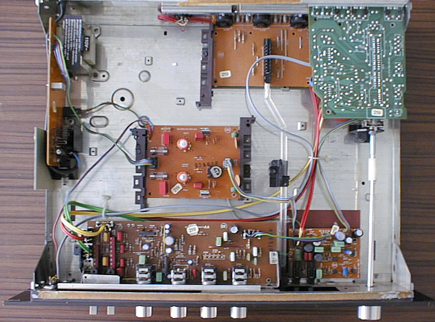
The STP 1 uses selen-based rectifiers in its power supply - the small, 4-legged red boxes with an AEG logo. These devices have a finite lifetime, so expect them to die some day. Otherwise, there is not much in the STP 1 that could break, apart from the usual problems with scratching pots. An yes, the STP 1 also belongs to the generation of devices that fights with broken power switches...
(taken from the service manual)
| Cabinet Parts | ||
|---|---|---|
| Position | Order No. | Designation |
| 501 | 309 796 047 | cabinet, brown |
| 309 796 049 | cabinet, champagner | |
| 502 | 309 863 991 | chassis |
| 503 | 309 833 584 | front mask, brown (STP 1) |
| 309 833 501 | front mask, champagner (STP 1) | |
| 309 833 599 | front mask, brown (CP 20) | |
| 309 833 600 | front mask, champagner (CP 20) | |
| 504 | 309 853 973 | handle for cabinet |
| 505 | 339 061 750 | rubber foot |
| 506 | 309 802 115 | control knob for range |
| 507 | 309 802 113 | control knob for treble, bass, |
| bass, volume | ||
| 508 | 309 800 131 | push button knob for noise, copy, |
| mono | ||
| 509 | 309 809 951 | toggle switch knob |
| 510 | 309 833 585 | knob cover |
| 511 | 309 921 921 | mains switch rod with knob |
| Electrical Parts | ||
| Position | Order No. | Designation |
| BS 5318 | 349 654 944 | AF adjust module |
| BS 5342 | 349 369 991 | input selector switch module |
| BS 5345 | 309 369 986 | copy module |
| BS 5351 | 309 362 014 | switch module |
| BS 5519 | 309 310 137 | mains transformer with fuse board |
| BS 5522 | 309 369 985 | power supply board |
| BU 1 | 309 672 921 | microphone socket |
| BU 2 | 309 672 922 | output socket |
| D 1 | 309 327 022 | LED FLV 110 red |
| FU 1 | 309 627 917 | fuse T 80 mA |
| 514 | 309 695 935 | power cord |
| 515 | 309 630 023 | mains switch |
| 516 | 309 632 947 | switch 2 x UM |
| AF Adjust Module | ||
| Position | Order No. | Designation |
| BS 5318 | 349 654 944 | AF adjust module |
| C 315 | 309 412 645 | Al-electr. cap. 47 µF / 25 V |
| C 318 | 309 412 655 | Al-electr. cap. 47 µF / 50 V |
| C 319/323 | 309 412 644 | Al-electr. cap. 47 µF / 16 V |
| C 320/324-326 | 309 410 634 | Al-electr. cap. 4.7 µF / 35 V |
| IC 301/302 | 309 368 212 | IC HA 1457 |
| R 316 | 309 511 068 | film var. resistor 2x100 kOhm - volume |
| R 344 | 309 511 069 | film var. resistor 2x25 kOhm - balance |
| R 354 | 309 511 070 | film var. resistor 2x100 kOhm - bass |
| R 373 | 309 511 071 | film var. resistor 2x100 kOhm - treble |
| S 301 | 309 639 971 | toggle switch 4 x UM |
| S 302 | 309 639 977 | toggle switch 5 x UM |
| Input Selector Switch Module | ||
| Position | Order No. | Designation |
| BS 5342 | 349 369 991 | input selector switch module |
| BU 301/302 | 309 679 503 | cinch socket |
| BU 303/304/305 | 309 672 801 | DIN socket, 5 contacts |
| C 301/312/ | 309 410 728 | Al-electr. cap. 4.7 µF / 40 V |
| 1301/1312 | ||
| C 306/1306 | 309 412 645 | Al-electr. cap. 47 µF / 25 V |
| C 308/1308 | 309 414 794 | Al-electr. cap. 100 µF / 35 V |
| C 316 | 309 410 634 | Al-electr. cap. 4.7 µF / 35 V |
| IC 301/1301 | 309 368 212 | IC HA 1457 |
| L 301/1301 | 309 249 053 | RF choke |
| S 301 | 309 639 005 | rotary switch, 6 positions |
| Copy Module | ||
| Position | Order No. | Designation |
| BS 5345 | 309 369 986 | copy module |
| BU 301/302/ | 309 679 503 | cinch socket |
| 304/308/309 | ||
| BU 305/306/310 | 309 672 801 | DIN socket, 5 contacts |
| S 301 | 309 635 911 | pressure switch 6 x UM |
| 518 | 309 921 922 | switch rod |
| Switch Module | ||
| Position | Order No. | Designation |
| BS 5351 | 309 362 014 | switch module |
| C 302 | 309 412 674 | Al-electr. cap. 47 µF / 40 V |
| C 306/1306 | 309 410 634 | Al-electr. cap. 47 µF / 25 V |
| C 501 | 309 414 694 | Al-electr. cap. 220 µF / 25 V |
| C 502/503 | 309 413 485 | Al-electr. cap. 100 µF / 25 V |
| D 301 | 309 325 927 | diode 1 N 4148 |
| L 301/1301 | 309 249 083 | filter coil 120 kHz |
| S 301/302 | 309 635 915 | pressure switch, noise/mono |
| T 301/1301 | 309 001 242 | transistor BC 550 C |
| T 302/1302 | 309 001 241 | transistor BC 238 C |
| Power Supply Board | ||
| Position | Order No. | Designation |
| BS 5522 | 309 369 985 | power supply board |
| C 503/509 | 309 414 770 | Al-electr. cap. 470 µF / 40 V |
| FU 501/502 | 309 627 906 | fuse T 100 mA |
| GR 501/502 | 309 320 928 | Se-rectifier B 30 C 400 A 5 |
| IC 501/502 | 309 368 178 | IC UA 78 MGU 1 C |
| L 501/502 | 309 249 053 | RF choke |
| R 502 | 309 504 402 | variable resistor 1 K/1/0.15 W |
| Mechanical Parts | ||
| Position | Order No. | Designation |
| 520 | 309 943 021 | shaft (input selector switch) |
| 521 | 309 928 904 | clutch |
| 522 | 309 900 295 | diode holder, 1-fold |
| 523 | 309 653 501 | fuse holder |