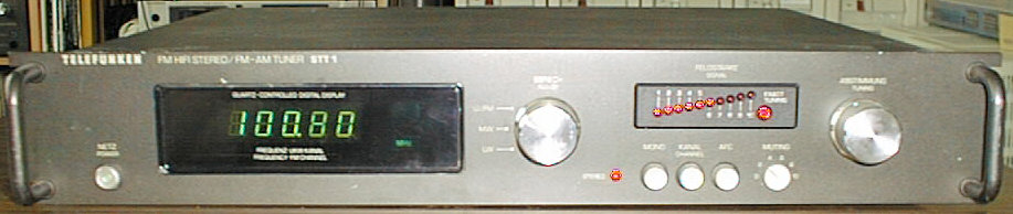


Analog Tuner with Digital Frequency Display
1980
The STT 1 is the 19-inch rackmount version of the CT 20 tuner. This tuner bears a lot in common with its 'smaller cousin' CT 10 - the same tuner board, already known from previous season's tuner TT 350, the same slim-line housing and most knobs have the same position. The only difference is the digital frequency display module:

The module is the same as used e.g. in the TRX 3000. The chip used for the digital clock is not present in the STT 1.
Variable Muting Level, Automatic Fine Tuning, Exact Tuning Indicator
(taken from the service manual)
| FM Receiver Section | |
|---|---|
| Wave Range: | FM = 87.6 ... 108 MHz |
| Circuits: | 11, 4 tunable |
| Sensitivity: | 0.7 µV at 60 Ohms |
| 1.4 µV at 240 Ohms | |
| Intermediate Frequency: | 10.7 MHz |
| IF Bandwidth: | 170 kHz |
| Selection: | >70 dB at ±300 kHz at antenna |
| Distortion Factor: | <0.5% Mono/<0.6% Stereo |
| (1 kHz, 40 kHz modulation) | |
| Range of Strength Display: | 1 µV-1 mV |
| AM Receiver Section | |
| Wave Range: | MW = 518 ... 1610 kHz |
| (579-185 m) | |
| LW = 148 ... 325 kHz | |
| (2027-937m) | |
| Circuits: | 5, 2 tunable |
| Intermediate Frequency: | 460 kHz |
| IF Bandwidth: | 4.5 kHz |
| General | |
| Semiconductors: | 16 Integrated Circuits |
| 21 Transistors | |
| 28 Diodes | |
| 12 LEDs | |
| Mains Voltage: | 220/110 Volts |
| Fuses: | Mains 220 V = 1 x T 125 mA |
| 110 V = 1 x T 125 mA | |
| Secondary 2 x T 315 mA, 1 x T 1 A | |
| Dimensions: | 482.6 x 80 x 350 mm |
| Wright: | 6.1 kg |

The STT 1 suffers from the same, simple failure as may other Telefunken devices in that era: a broken mains switch! Symptoms are that the device cannot be turned on or off any more, or a power switch button that doesn't move at all. The problem is the the 'ball pen' mechanics consist of a piece of metal moving in a plastic bearing, and the plastic wears out over time. Replacing the switch is not that a problem, given you can get one that fits precisely - you need a variant that has both pins on the underside (for soldering into the PCB) and soldering contacts on the upper side (for connecting the power cord).
(taken from the service manual)
| Cabinet Parts | ||
|---|---|---|
| Position | Order No. | Description |
| 501 | 309 796 047 | cabinet, brown |
| 501a | 309 796 049 | cabinet, champagne |
| 502 | 309 833 576 | front mask, brown (STT 1) |
| 502a | 309 833 603 | front mask, champagne (STT 1) |
| 309 833 604 | front mask, brown (CT 20) | |
| 309 833 605 | front mask, champagne (CT 20) | |
| 503 | 309 863 989 | frame cassis |
| 504 | 309 833 577 | cover for indicator |
| 505 | 309 833 578 | cover for counter |
| 506 | 309 833 579 | counter mask |
| 508 | 309 921 921 | mains switch rod with button |
| Electrical Parts | ||
| Position | Order No. | Description |
| BS 5108 | 349 362 015 | AM-FM-AF-O/P and range rotary switch module |
| BS 5507 | 309 369 960 | power supply unit for frquency counter |
| BS 5533 | 309 310 136 | mains transformer with fuse board |
| BS 5606 | 349 350 925 | FM mixing unit with AM tuning capacitor |
| BS 5707 | 349 395 989 | frequency counter |
| BS 5730 | 349 395 022 | LED indicator (field strength) |
| BS 5769 | 309 369 977 | impedance transformer for freq. counter |
| BS 5770 | 309 362 012 | switch board (type of operation) |
| AM-FM Switch Module | ||
| Position | Order No. | Description |
| BS 5108 | 349 362 015 | AM-FM-AF-O/P and range rotary switch module |
| BU 101/S 101 | 309 670 923 | AM antenna socket with switch |
| BU 102 | 309 670 927 | combined antenna socket |
| BU 103 | 309 672 801 | DIN socket, 5 contacts |
| BU 104/105 | 309 679 503 | Cinch socket |
| C 113 | 309 450 605 | disc trimmer N 750 10/40/250 V |
| C 121 | 339 582 048 | Al-electr. cap. 10 µF/10 V |
| C 127 | 309 410 641 | Al-electr. cap. 4.7 µF/25 V |
| C 136/165/184 | 309 413 482 | Al-electr. cap. 100 µF/25 V |
| C 138/146 | 309 411 673 | Al-electr. cap. 22 µF/10 V |
| C 141/150/161/ | 309 410 634 | Al-electr. cap. 4.7 µF/35 V |
| 179 | ||
| C 152/162 | 309 410 655 | Al-electr. cap. 2.2 µF/25 V |
| C 153 | 309 412 645 | Al-electr. cap. 47 µF/25 V |
| C 177 | 309 414 737 | Al-electr. cap. 2200 µF/40 V |
| C 182/183 | 309 410 688 | Al-electr. cap. 1 µF/25 V |
| D 104/105/106/ | 309 325 027 | diode 1 N 4148 |
| 108/109/110 | ||
| FI 101 | 309 103 952 | ceramic filter 10.7 MHz |
| FI 102 | 309 111 802 | band filter |
| FI 103 | 309 103 953 | ceramic resonator 460 kHz |
| FI 104 | 309 220 031 | IF filter coil |
| FI 105/106 | 309 103 948 | ceramic filter 19 kHz/38 kHz |
| FU 101 | 309 627 901 | fuse T 315 mA |
| GR 101 | 309 320 602 | rectifier B 30 C 350/250 KP |
| IC 101 | 309 368 133 | IC TDA 1046 |
| IC 102 | 309 368 094 | IC CA 3089 E |
| IC 103 | 309 368 173 | IC TCA 4500 A |
| IC 104 | 309 368 130 | IC UA 78 GU 1 C |
| L 101 | 309 259 919 | choke |
| L 102 | 309 309 950 | antenna transformer |
| L 103 | 309 250 930 | RF choke 2200 µH |
| L 104 | 309 207 922 | pre-circuit coil MW |
| L 105 | 309 208 911 | pre-circuit coil LW |
| L 106 | 309 259 934 | RF choke |
| L 107/108 | 309 218 922 | oscillator coil LW |
| L 111 | 309 220 083 | filter coil 18 MHz |
| L 112 | 309 220 046 | filter coil 10.7 MHz |
| R 157 | 309 500 071 | variable resistor 5 K/1/0.15 W |
| R 166 | 309 509 401 | variable resistor 10 K/1/0.07 W |
| S 104 | 309 639 003 | rotary switch, 6 positions |
| T 101 | 309 001 238 | transistor BF 441 |
| T 102/103/107/ | 309 001 248 | transistor BC 308 B |
| 109 | ||
| T 104 | 309 001 227 | transistor BF 256 B |
| T 105/106/110 | 309 001 949 | transistor BC 238 B |
| T 108/111/112 | 309 001 241 | transistor BC 238 C |
| 520 | 309 689 904 | IC socket, 16 contacts |
| Power Supply Unit | ||
| Position | Order No. | Description |
| BS 5507 | 309 369 960 | power supply unit for frquency counter |
| C 517 | 309 414 785 | Al-electr. cap. 2200 µF/16 V |
| C 518 | 309 414 770 | Al-electr. cap. 470 µF/40 V |
| C 520 | 309 414 729 | Al-electr. cap. 1000 µF/40 V |
| C 521 | 309 413 468 | Al-electr. cap. 100 µF/16 V |
| D 515-518 | 309 325 953 | diode 1 N 4003 |
| D 522 | 309 325 634 | diode BZY 85 C 16 |
| FU 515 | 309 627 919 | fuse T 1 A |
| FU 516 | 309 627 901 | fuse T 315 mA |
| IC 515/516 | 309 368 130 | IC UA 78 GU 1 C |
| R 517 | 309 504 805 | variable resistor 500/1/0.15 W |
| FM Mixing Unit | ||
| Position | Order No. | Description |
| BS 5606 | 349 350 925 | FM mixing unit with AM tuning capacitor |
| C 105/116/122 | 309 400 967 | tuning capacitor |
| C 625 | 309 461 703 | Ta-electr. cap. 22 µF/6.3 V |
| D 601 | 309 327 956 | diode SMV 709 |
| D 602 | 309 325 027 | diode 1 N 4148 |
| FI 601 | 309 220 013 | IF filter |
| L 601 | 309 209 930 | FM antenna coil |
| L 602 | 309 209 931 | pre-circuit coil |
| L 603 | 309 219 935 | oscillator coil |
| L 604 | 309 249 171 | intermediate circuit coil |
| L 605 | 309 250 943 | RF choke |
| T 601 | 309 005 007 | transistor 2 SK 55 D |
| T 602/603 | 309 001 933 | transistor BF 241 |
| Frequency Counter | ||
| Position | Order No. | Description |
| BS 5707 | 349 395 989 | frequency counter |
| C 701 | 309 461 703 | Ta-electr. cap. 22 µF/6.3 V |
| C 722 | 309 450 806 | disc trimmer N 750 6/25/250 V |
| C 728 | 309 410 698 | Ta-electr. cap. 4.7 µF/35 V |
| C 733 | 309 413 508 | Ta-electr. cap. 100 µF/10 V |
| D 700-705 | 309 325 927 | diode 1 N 4148 |
| D 706/707 | 309 325 064 | diode 1 N 4848 |
| D 708 | 309 325 965 | diode BZY 85 C 5 V 6 |
| D 709 | 309 327 037 | diode 6.2 V |
| IC 700 | 309 368 112 | IC SN 74 LS 112 N |
| IC 701/702 | 309 368 207 | IC SN 74 LS 90 N |
| IC 703/705 | 309 368 208 | IC SN 74 LS 74 N |
| IC 704 | 309 368 115 | IC TL 7404 N |
| IC 707 | 309 368 117 | IC DFU 101 |
| IC 708 | 309 368 176 | IC IC SN 74 S 04 spec. |
| L 701 | 309 259 919 | choke |
| L 703 | 309 250 935 | RF choke |
| L 704 | 309 259 933 | RF choke |
| L 705/706 | 309 250 934 | RF choke |
| LA 700/701 | 309 621 968 | bulb 4.3 V/100 mA/0.43 W |
| QU 700 | 309 335 992 | crystal 5.12 MHz |
| R 740 | 309 504 995 | variable resistor 50 KOhm |
| T 700 | 309 001 933 | transistor BF 241 P |
| T 701 | 309 001 108 | transistor BC 307 B |
| T 702 | 309 001 120 | transistor BC 213 |
| V 700 | 309 395 962 | fluorescent display |
| LED Indicator | ||
| Position | Order No. | Description |
| BS 5730 | 349 395 022 | LED indicator (field strength) |
| 522 | 309 900 292 | diode holder, 12-fold |
| D 701-710 | 309 327 053 | LED CQY 85 red |
| D 711 | 309 327 022 | LED FLV 110 red |
| IC 701 | 309 368 231 | IC U 254 B |
| IC 702 | 309 368 230 | IC U 244 B |
| Impedance Transformer | ||
| Position | Order No. | Description |
| BS 5769 | 309 369 977 | impedance transformer for freq. counter |
| L 705 | 309 259 919 | choke |
| T 712 | 309 001 933 | transistor BF 241 P |
| T 713/714 | 309 001 949 | transistor BC 238 B |
| Mechanical Parts | ||
| 525 | 309 926 808 | tension roller for cord |
| 526 | 309 981 802 | spring for tension roller |
| 527 | 309 926 983 | cord disc |
| 528 | 309 928 904 | clutch |
| 529 | 309 870 925 | dial cord |
| 530 | 309 943 020 | tuning shaft |
| 531 | 309 927 909 | flywheel |
| 532 | 309 900 295 | diode holder |
| 533 | 309 653 501 | fuse holder |
| 534 | 309 928 904 | clutch for shaft |
| 535 | 309 943 022 | shaft for range |